


Air-cooling for Rear mounted Engines
Page 66
If you've noticed an error in this article please click here to report it so we can fix it.
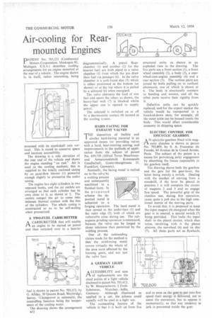
PATENT No. 703,121 (Continental Motors Corporation, Muskegon 82, Michigan, U.S.A.) describes cooling arrangements for an engine mounted at the rear of a vehicle. The engine shown is, in itself, rather interesting, being
mounted with its crankshaft axis vertical. This is stated to conserve space and increase accessibility.
The drawing is a side elevation of the rear end of the vehicle and shows the engine standing "on end." Air is used as the cooling medium; this is supplied to the totally enclosed casing by an axial-flow blower (1) powerful enough slightly to pressurize the entire casing.
• The engine has eight cylinders in two opposed banks, and the air outlets are arranged so that each cylinder has its own close to it, as shown at 2. The outlets compel the air to come into intimate thermal contact with the fins of the cylinders. The whole casing is constructed so as to be self-sealing when pressurized.
A TWO-FUEL CARBURETTER A CARBURETTER that will enable an engine to be started on petrol and then switched over to a heavier
fuel is shown in patent No. 703,113, by G. Allday, 30 Queens Road, Weybridge, Surrey. 'Changeover is automatic, the controlling function being the temperature of the cooling water.
The drawing shows the arrangement a32 diagrammatically. A petrol floatchamber (1) and another (2) for the heavier fuel, are both piped to a valve chamber (3) from which the jets draw their fuel via passages (4). In the valve chamber is a cork-faced disc (5) which is either positioned at the bottom (as shown) or at the top where it is pulled by a solenoid (6) when energized.
The valve obstructs the feed of one fuel and opens the other; as shown, the heavy-fuel well (7) is blocked whilst the upper one is opened to supply petrol.
The solenoid is switched on or off by a thermostatic contact (8) located in the cooling system.
HARD FACING FOR EXHAUST VALVES E deposition of Stellite and similar hard-facing material is an approved means for providing valves with a hard, heat-resisting seating, and improvements in the methods of application form the subject of patent No. 699,520 (Alfred Teves Maschinenund Armaturenfabrik Kommandit Gesellschaft, Gustavsburgstrasse 31, Frankfurt, Germany).
Normally, the facing metal is melted on to the valve by a welding process ' and subsequently machined to a finished form. In the proposed scheme the de posited metal is subjected to a forging operation. The hard metal 's then spread to the under-face (I) and the outer edge (2), both of which are vulnerable areas during use. The subsequent grinding operation is minimized, because the valve can be forged to closer tolerance than permitted by the welding process.
One of the outstanding claims made for the method is that the reinforcing metal covers virtually the whole of the area most affected by the burning gases, and not just the valve face.
A GERMAN LIGHT VEHICLE
ACCESSIBILITY and ease of replacements are the chief points of a light vehicle disclosed in patent No. 701,413, by-W, Messerschmitt, 2 Frohlichstrasse, Munchen -Solln, Germany. Although illustrated as applied to a car, the scheme could equally well be used in a light van.
The outstanding feature of the vehicle is that it is built up from live
structural units, as shown in an exploded view in the drawing. The five parts are a front section (1), a front wheel assembly (2), a body (3), a rearwheel-cum-engine assembly (4) and a rear section (5). The various parts are joined by bolts pulling on to resilient abutments, one of which is shown at 6. The body is structurally resistant to bending and torsion, and all the other parts receive their rigidity from it.
Defective units can be quickly replaced, and for the export market the vehicle would be transported in a knocked-down state; for example, all the outer units can be housed inside the body. This would effect considerable economy in shipping space, ELECTRIC CONTROL FOR EPICYCLIC GEARBOX
AN ePicyclic gearbox fitted with magnetic clutches is shown in patent No. 702;809, by S. A. Francaise du Ferodo, 64 Avenue de la Grand Arm6e, Paris. The subject of the patent is a means for preventing jerky engagement by absorbing the forces responsible in the gearbox itself.
The drawing shows both the gearbox and the gate for the gear-lever, the latter being merely a switch. Dealing with the matAer of starting from a standstill, if the lever be placed in position 1 it will complete the circuit of magnets 2 and 3 and so engage first speed. The powerful grip of the clutches can, during this operation, cause quite a jerk due to the high rotational inertia of the moving parts.
To avoid this, it is proposed to keep the input magnet (4) energized when the gear is in neutral, a special switch (5) being provided. This locks the input shaft to the planet carrier, which then turns, revolving with it the planet pinions, the sunwheel (6) and its disc (7). All these parts act as flywheels,
and as soon as the geas't pat into first speed their energy is delivered, not to assist the movement, but to oppose it momentarily, so that any tendency to jerk is prevented inside the gear.