


Trailer Pump with Strong Protecting Cage
Page 36
If you've noticed an error in this article please click here to report it so we can fix it.
A Resume of Recently Published Patent Specifications
SMALL portable fire-pumps are usually required to go into action with the utmost celerity, and the conditions of service are such that accidents aie likely to occur. A safety cage to minimize the risk of the unit being put out of action is shown in patent No. 544,459, by Sigmund Pumps (Great Britain), Ltd., and M. Sigmund, Bush House, Aldwych, London, W.C.2.
It is proposed to surround the pump and engine with a cage made of heavygauge steel tubing, one elevation of which is shown in the drawing. In a view at right angles to that given here, the cage is substantially elliptical in outline, but has a flat base to rest upon. Extending handles may be provided, so that the unit can be manually carried to any desired spot.
In the event of collision, overturning or other mishap, the cage would afford considerable protection to the mechanism, whilst its shape lends itself easily to rolling back to the upright position.
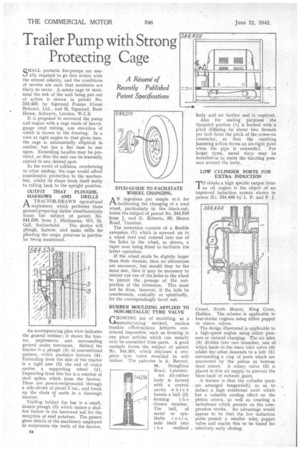
OUTFIT THAT PLOUGHS, HARROWS AND DRILLS
ATRACTOR-DRAWN agricultural implement. which performs three ground-preparing duties simultaneously forms the subject of patent No. 544,539, from J. Hiirlimann, Wil, St.
Gall, Switzerland. The device will plough, harrow, and make drills for planting the crops, potatoes in particular being mentioned.
An accompanying plan view indicates the general scheme ; it shows the tractor, implements and surrounding ground under treatment. Behind the tractor is a plough (5) of conventional pattern, which produces furrows (4). Extending from the side of the tractor is a rigid arm (2) the end of which carries a supporting wheel (1). Depending from this bar is a number of steel spikes which form the harrow. These are power-reciprocated through a side-stroke of about 3 ins., and break up the clods of earth in a thorough manner.
Trailing behind the bar is a small, double plough (3) which makes a shallow furrow in the harrowed soil for the reception of seed potatoes. The patent gives details of the machinery e ployed to reciprocate the teeth of the larrow. STUD-GUIDE TO FACILITATE WHEEL CHANGING
A'ingenious _yet simple toal for facilitating the changing of a road. wheel, particularly in the black-out, forms the subject of patent No. 544,510 from J. and G. Roberts, 26, Manor toad, Taunton.
The invention consists of a flexible extension. (1) which is screwed on to a wheel stud and entered into one of the holes in the wheel, as shown, a taper nose being fitted to facilitate the latter operation.
If the wheel .studs be slightly larger than their threads, then no alterations are necessary, but should they be the same size, then it may be necessary to reamer out one of the holes in the wheel to permit the passage of the nutportion of the extension. This must not be done, however, if the hole be countersunk, conically or spherically, for the correspondingly faced nut.
RUBBER MOULDING APPLIED TO NON-METALLIC TYRE VALVE
GROWING use of moulding, as a manufacturing method, renders feasible ceestructions hitherto considered impossible, such as forming in one piece articles which can usually only be assembled from parts. A good example forms the subject of patent No. 544,261, which discloses a onepiece tyre valve moulded in soft rubber. The patentee is A. Barrett, 26, Stoughton Road, Leicester.
An all-rubber body is formed with a central cavity which houses a ball (2) forming the closure member. The ball, of metal or syn thetic resi n, beds itself into t h e resilient
body and no further seal i3 required. Also for sealing purposes the threaded portion (I) is formed with a pitch differing by about two threads per inch from the pitch of the screw-on connector, so that the resulting jamming action forms an air-fight joint when the pipe is connecteJ. For larger tyres, metal rins may be moulded-in to resist the bumting pressure around the body.
LOW CYLINDER PORTS FOR EXTRA INDUCTION
TO obtain a high specific output from an oil engine is the object of an improved induction system shown in patent No. 544,446 by L. P. and P. J.
Croset, North Mount, King Cross, Halifax. The scheme is applicable to • four-stroke engines using either poppet or sleeve valves.
The design illustrated is applicable to a high-speed engine using either pressure or natural charging. The air inlet (3) divides into two branches, one of which leads to the main inlet valve (4) whilst the other descends to a belt (I) surrounding a ring of ports which are uncovered by the piston at bottom dead centre. A rotary valve (2) is placed in this air supply to prevent the blow-back of exhaust gases.
A feature is that the cylinder ports are arranged tangentially so as to induce a high rotational swirl which has a valuable cooling effect on the piston crown, as well as creating a turbulence which persists on the compression stroke. An advantage would appear to be that the low induction ports permit a smaller inlet poppet valve and enable this to be timed for , relatively early closing,