


THE SPROULE ENGINE.
Page 32
If you've noticed an error in this article please click here to report it so we can fix it.
A Resum6 of Recently Published Patents.
An interesting and novel type of engine is the subject of a patent this .week by A. H. Sproule. Apparently it has the advantages of being more flexible than existing types, as well as more efficient, particularly when the efficiency is considered over a wide range of loads and speeds; while, finally, it is reversible.
• The engine is built up with the cylinders'arranged in pairs, so that each pair of cylinders constitutes what may be termed a unit engine. The piston of each cylinder is connected to a separate crank on an independent crankshaft, the two shafts being geared together in such a manilas that one makes two revolutions to each one complete turn by the other. As a natural result, one piston makes twice as many strokes as the other, and, since the two cylinders have a common combustion chamber, it follows that while one piston makes only two strokes per cycle of operation, the other makes four. Furthermore, the relative setting of the two cranks with regard to one another may be varied. That is to say, one of them may be set in advance of, or a little behind, the other, thus enabling the volume of the charge to be varied while keeping the compression pressure the same. Negative advance of one piston with respect to the other, will have the effect of reversing the engine, as will be ehown later.
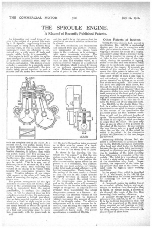
The precise arrangement of the two cylinders of a pair does not matter. That shown in the accompanying illustration, which is reproduced from the patent specification, is perhaps the simplest farm. It will he observed that the two cylinders are side by side. On each crankshaft is mounted a helical gearwheel, the two being coupled together by a third wheel on a shaft at right angles to the crankshafts, the gearing being such that one crank revolves at twice the speed of the other. Provision is made, by means of a fork and controlling gear, to move this cross-shaft, with its gearwheel, to z36 and fro, and it is by this means that the position of one crank relative to the other is altered.
The two crankcases are independent and isolated from one another. Frelimiary compression of the charge takes place in the crankcase, as is customary with many two-stroke engines. The charge thus compressed is transferred by means of a single valve, which operates both as inlet and transfer valve, to a suitable receiver, whence it is conducted to the cylindere, which it enters by means of an ordinary mechanically-operated valve. Exhaust takes place through a series of ports in the wall of one cylin ier, the ports themselves being governed as to their area. by means of a hand. operated valve, which may close !Attiei one or two of the three rows of ports As shown in the drawing, the two cranks are 'in phase," so that the two pistons reach the top of their strokes at the same instant. In this position the effective combustion space above the two pistons is at a minimium this position being the one most suitable for running under light loads at high efficiency—with low fuel consumptionUnder heavy load the setting of the two cranks is altered so that the one in the larger cylindei is slightly advanced in respect to the other. Bo arranged, the actual volume of the compression space is increase& and as the throttle valve will necessarily be opened for the heavier loads, a greater weight of charge will be induced into the cylinder, thus maintaining the actual compression pressure at a constant. Alternatively, the effective volume of the combustion :Taco may be increased without increasing the amount of opening of the' throttle valve. The effective compression will in that manner be de creased, thus enabling the engine to run slowly and steadily, even when undei comparatively heavy loads. The patent specification is numbered 163,735.
Other Patents of Interest.
Tilling-Stevens Motors, Ltd., patent in specification No. 163,792 a mechanical tipping gear for use in connection with their petrol-electric chassis. The actual tipping is effected by means of a longitudinalaicrew along which a nut may move. The nut is coupled by means of a pair of links to the under side of the. body which, during the operation of tipping, slides to the rear and over-balances when stops on its underside come into contact with pins on the chassis. It is mainly on account of the method of driving the screw that this patent is taken out. On the front end of the screw is mounted a large spur wheel of such a size that it can conveniently engage with a sliding pinion mounted on splines on an extension ofetheanotoreshaft. The latter does not drive the propeller ;shaft direct, but through the medium of this pinion which, when disengaged from the.epur wheel on the screw, slides into mesh with internal teeth mounted at the front end of a short coupling which is supported in hall bearings on a cross-member of the frame, and which is designed at its rear end to receive the front end of the propeller shaft.
No. 163,610, by the Austin Motor Co., Ltd., is a rather ingenious but extremely simple two-in-one spud for tractor wheels. In the course of the specification the patentees point out that different conditions a soil call for different lengths of spuds. The specification describes one in the form of an angle, of which one flange is longer than the other. The spud may take up one or otherof two positions on the wheel of the tractor. In one position the long flange acts as a spud and the other lies on the rim of the wheel to which it is bolted: in the alternative position the ,funetions of the two flanges are reversed Armstrong-Siddeley Motors, Ltd., deseribe•a constniction,of air-cooled cylinder in No. 163,635, having an aluminium alloy heed and steel body, the fastening between the two parts being particularly designed to eliminate loss of compression due to breaking of the joint resulting from differences in expansion of the two metals. The joint is a cone-shaped one, in which a steel collar embraces the end of the aluminium alloy head. Consequently, the expansion of the latter being greater than that of the former, the joint tends to tighten under working conditions.
In the petrol filter, which is described by W. F. McDurmicl, in No. 163,784, the gauze filtermay be cleaned periodically by reversing the flow of the petrol through it.
A, Campbell, makes the: cooling fins of an air-cooled cylinder hollow, and so arranges the exhaust Loin the engine that it draws, by ejector action, a current of air through the inside of the Ens, thus increasing their cooling efficiency.
A peculiar change-speed gear is the subject of No. 163,753, by II. W. Home, It Is for indirect transmission only, the rims of the gearwheel on the main shaft being mounted on ball bearings on their hubs, and made operative alternatively by being wedged into close contact with one or other of those hubs.