


LOW-DRAG TRAILERS
Page 33
Page 34
If you've noticed an error in this article please click here to report it so we can fix it.
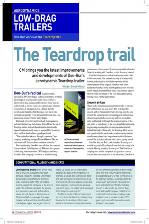
Don-Bur works on the Teardrop Mk2
The Teardrop trail
CM brings you the latest improvements and developments of Don-Bur’s aerodynamic Teardrop trailer
Words: David Wilcox Don-Bur’s radical Teardrop trailer, unveiled in 2007, was shaped by little more than a working knowledge of aerodynamics and a vision of what a slippery, low-drag trailer could look like. There were no scale models in a wind tunnel, no sophisticated software programmes. It all depended on a hunch that the aerodynamic beneits of the humped roof line would outweigh the penalty of the increase in frontal area – the hump adds around 0.5m to trailer height.
The hunch proved correct. Feedback from operators indicates that average fuel savings derived from the use of Teardrop trailers instead of equivalent conventionally shaped trailers currently stand at around 11%. Teardrop’s effect on Don-Bur has been equally profound.
“That trailer has taken us through a recession,” says company marketing manager Richard Owens. “But we can’t stand still. Teardrop has to continue to evolve.” That explains why Don-Bur has called on the power of Computational Fluid Dynamics (CFD) and the expertise of Brackley, Northants-based CFD design consultancy TotalSim. This company’s brief was to model the drag performance of the current Teardrop to establish a baseline. Now it is working with Don-Bur to take Teardrop forward.
TotalSim’s baseline model of Teardrop includes a Daf CF85 tractor unit. The trailer is actually a Teardrop Mk2 boxvan, introduced in 2010. It incorporates all the characteristics of the original Teardrop, with a few additional features. These include partial covers over the trailer wheels, a small (65mm either side) inward taper of the side walls just ahead of the rear frame, plus vertical turning vanes on the rear corners.
Smooth airflow
There is also panelling underneath the trailer to enclose the void between the side skirts. This is designed to smooth airlow beneath the trailer, leaving only the area around the axles exposed for running gear maintenance. This arrangement also scoops up air from around the axles and funnels it through the rearmost section of the side skirts to exit cleanly at the rear, hopefully repressurising the drag-inducing low-pressure area immediately behind the trailer. This is why the Teardrop Mk 2 has no rear panel, with the usual under-run bar and its vertical stanchions replaced by a large diameter tube that runs around the periphery of what looks like a gaping mouth.
TotalSim director Rob Lewis describes Teardrop as a sensible approach. Don-Bur will soon ind out exactly how sensible. Having modelled Teardrop in CFD, TotalSim is carrying out a similar analysis of an equivalent conventional trailer for comparison. In the meantime, Don-Bur is getting to grips with TotalSim’s analysis of the Teardrop design. The headline igure is a creditable drag coeficient (Cd) of 0.437 for the whole outit, measured at a yaw angle of one degree. At 56mph the total aerodynamic drag force resisting forward movement is 1,838N. Of that, 82% is acting on the tractor unit; only 18% is acting on the trailer.
Unsurprisingly, the bluff front of the tractor unit accounts for around half the outit’s total drag force. Less obvious is the second biggest source of drag – the rear face of the cab. TotalSim’s pressure co-eficient modelling shows how the low air pressure in the gap between tractor unit and trailer means there is low pressure on the cab’s rear face and, hence, plenty of drag.
This effect occurs again immediately behind the trailer, so the very low pressure on the rear shutter is the third and inal of the three biggest sources of drag. At least Teardrop’s downward sloping roof reduces this last issue because the slope (and low-height rear) cuts the size of this turbulent, low-pressure region behind the trailer. TotalSim’s CFD analysis of a conventional trailer will quantify the difference.
Cornered
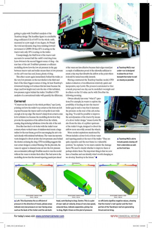
“Corners set the scene for the whole problem,” says Lewis, pointing out how the trailer’s top corners at the front are left exposed because the tractor unit’s roof spoiler is not wide enough at its top edge. The tractor’s sharp front corners come in for criticism too, because the modelling shows how they provoke the separation of the airlow from the vehicle, causing drag-inducing turbulence down the side of the unit.
Don-Bur has tried to do better with the trailer’s rear corners, where vertical vanes of stainless-steel create a large radius for the rear frame, good for encouraging the air to detach cleanly with minimal turbulence. The vanes incorporate vents designed to divert air into the low-pressure area behind the shutter, reducing the drag. CFD modelling suggests this rear corner design is a mixed blessing. On the plus side, the vanes do appear to channel some air into the low pressure area as intended, although TotalSim needs to run the model without the vanes to isolate their effect. The bad news is the modelling shows that the inward-tapering panels just ahead of the vanes are less effective because their edges stand just a couple of millimetres proud of the sidewalls, suficient to create a tiny step that disturbs the airlow at the point where it should be turned smoothly inwards.
Having constructed the Teardrop baseline model, CFD makes evaluation of modiications relatively quick and inexpensive, says Lewis. The process is automated so that a tweak proposed one day can be modelled overnight and its effects on the Cd value can be with Don-Bur the following morning.
Owens already has some “what if” questions. For example, he wants to explore the possibility of feeding air into the tractor/ trailer gap in such a way that it increases the pressure on the rear of the cab, reducing drag. “It could be possible to improve the aerodynamics of the tractor by means of a clever trailer design,” muses Lewis. He also loats the idea of a splitter upstream of the trailer’s bogie, designed to divert the airlow more smoothly around the wheels.
More modest aspirations mentioned by Owens include a closer look at those vanes and tapering panels at the rear of the trailer. “They are quite expensive and the rear frame is a vulnerable position,” he explains, “so we must consider the damage factor. We need to decide whether to improve them or perhaps delete them. The important thing is that we now have a baseline and can identify what’s worth changing as we develop Teardrop in the future.” ■
COMPUTATIONAL FLUID DYNAMICS (CFD)
CFD modelling breaks down airflow into a host of tiny cells, calculating how each behaves. TotalSim’s Teardrop CFD model comprised a mesh of around 30 million cells, extending up to 100m behind the truck to capture the behaviour of the air in its wake. The software calculates the velocity and pressure in each cell as the vehicle travels through the air, in this instance at 56mph and with a yaw angle (the angle between airflow and direction of travel) of one degree. Higher yaw angles produce higher Cd values, so it is important to establish the basis of the modelling. For example, a typical artic (with boxvan trailer and cab-roof spoiler) is likely to have a Cd of around 0.6 with zero degrees of yaw, but at six degrees – reckoned to be a typical real-world figure – so-called ‘wind-averaged’ Cd is likely to be just over 0.7.
TotalSim’s cluster of 48 computers took six hours to model Teardrop, making many thousands of calculations. Rob Lewis explains that instead of using the iterative process of making changes to the configuration and then re-running the modelling it is possible to give CFD free rein to arrive at the optimum solution, constrained only by criteria such as minimum internal dimensions and legal limits. Wind tunnels big enough to take trucks are scarcer than hen’s teeth and time spent inside them is costly. So too is the task of making scale models for use in smaller tunnels. “CFD gives quick, cost-effective and accurate answers,” says Lewis.