


ASPECTS OF BUS-0 ASSIS MAINTENANCE
Page 50
Page 51
Page 52
If you've noticed an error in this article please click here to report it so we can fix it.
N. one can visit the Portslade maintenance works of Southdown Motor Services, Ltd., without being impressed not only by the quality of the workmanship displayed, but also by the numerous machines and methods which are employed, partly to facilitate the work and partly to render the vehicles more efficient after overhaul than they were before treatment.
Some of the processes and devices developed by the maintenance staff of the company have proved so practical and advantageous that they have been adopted by accessory and vehicle makers, and thus rendered available to other operators. One striking example of this is the " Snapshut" tap, which is being manufactured by Rotherham and Sons, Ltd., Coventry, and which will be described in an early issue.
How Cylinders are Bored and Honed.
Some of the machines. etc„ to which we refer, are neither new nor the products of the Portslade works, but all present points of interest as means for promoting efficiency. Our first visit was, for instance, to a Storm boring machine operated by a E.T.H. motor. This has a taper mandrel expanding six cutters, by which cylinders are machined to within .002 in. of the finished size and then honed on another Storm machine.
The hone carriers are centrally pivoted in a type of chuck havi„ng two arms, and the spring tension on these carriers is adjustable by means of a central screw. They are normally set to open, when free, about i in. wider than the diameter of the cylinder. This gives the correct pressure on the carborunduzn hones, which are being washed with paraffin the whole of the time, and last from four to five months.
It takes about 19 minutes to bore each cylinder, about .02 in. being removed in one cut; the honing involves from a quarter to half an hour.
Where sleeves are employed they axe obtained unfinished, turned externally, pressed into the cylinders and bored and honed after this operation, for it has been found that if the sleeves be finished first they may become distorted after the insertion. This applies only to the substitution of new sleeves for old, because, after use, the cylinders are usually out of true. With new cylinders, sleeves can be pressed in dead to size.
Various methods are utilized in connection with the reseating of valves. In some cases plain sleeves are used with a press fit of .005 in.
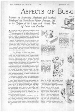
A type of sleeve of particular interest has been developed, and is now being marketed by Wellworthy, Ltd., Hants. Advantage is taken of the spring of the metal in such a manner that, when the new seating is pressed into the cylinder, parts of it spread into grooves cut in the block Each seating is cut through near its 432
base and at opposite sides, the Outside width of the slot thus formed being l in., and as the cutter is circular the width inside the seating is less.
This is important because into each slot thus formed is inserted a shim of thin brass or steel ; it serves no duty so far as locking is concerned, but merely prevents the sides of the slot from being closed together under the pressure of insertion. When in position, the material below each slot springs outwards to the extent of .005 in. arid keys into the slots An the cylinder casting, the shims remaining in position, where they are safe as they cannot fall out, The width of the milling cutter employed is .016 in. Of course, to remove a seating of this description it is necessary to cut it with a chisel.
It is noteworthy that whilst the cylinder heads are overhauled after every 25,000 miles of running, the seatings do not require replacement until after 50,000 miles.
In connection with cylinder liners on Titan vehicles, we learn that two lives are obtained from each sleeve, the second boring being to a standard of .025 in. above the original.
Brake drums, when worn, have hydraulically pressed into them spring steel sleeves in. thick, made from strip steel, welded together after rolling into circular form. The outsides are not touched, but the insides are ground after insertion. Additional security is afforded by rivets. This method can safely be employed with pressed-steel drums, but som-t1 older-type cast-iron drums will fracture.
Crankshafts are trued up on a Landis grindet, and it is usually found that the whole shaft can be rectified by removing a maximum of .005 in. to .008 in. along the length.
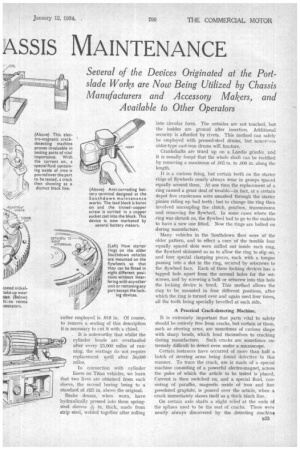
It is a curious thing, but certain teeth on the starter ritigs of flywheels nearly always wear in groups spaced equally around them. At one time the replacement of a ring caused a great deal of trouble—in fact, at a certain depot five crankcases were smashed through the starter pinion riding up bad teeth ; but to change the ring then involved uncoupling the clutch, gearbox, .transmission and removing the flywheel. In some cases where the ring was shrunk on, the flywheel bad to go to the makers to have a new one fitted. Now the rings are bolted on during manufacture.
Many vehicles in the Southdown fleet were of the older pattern, and to effect a cure of the trouble four equally spaced slots were milled out inside each ring, the flywheel skimmed so as to allow the ring to slip on, and four special clamping pieces, each with a tongue passing into a slot in the ring, secured by setscrews to the flywheel face. Each of these locking devices has a tapped hole apart from the normal holes for the setscrews, and by screwing a bolt or setscrew into this hole the locking device is freed. This method allows the ring to be mounted in four different positions, after which the ring is turned over and again used four times, all the teeth being specially bevelled at each side.
A Practical Crack-detecting Machine.
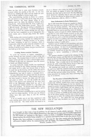
It is extremely important that parts vital to safety should be entirely free from cracks, but certain of them, such as steering arms, are sometimes of curious shape with sharp bends, which lend themselves to cracking during manufacture. Such cracks are sometimes extremely difficult to detect even under a microscope.
Certain instances have occurred of more than half a batch of steering arms being found defective in this manner. To trace the crack, use is made of a special machine consisting of a powerful electro-magnet, across the poles of which the article to be tested is placed. Current is then switched on, and a special fluid, consisting of paraffin, magnetic oxide of iron and fine powdered graphite, is poured over the article, when a crack immediately shows itself as a thick black line.
On certain axle shafts a slight relief at the ends of the splines used to be the seat of cracks. These were nearly always discovered by the detecting machine 333 before too late, but in some cases fractures actually occurred within two months of the test. A cure was effected by omitting,the relief, and the shafts are now made of 90-ton instead of 50-ton tensile steel.
The crack-detecting machine is shown in a sketch. The coil former is a brass tube 10 ins. long and 2i ins. outside diameter, the brass flanges being 51, ins. diameter and in. thick, the distances between them being si ins. It is wound with 6 lb. 10 oz. of 30 s.w.g. wire, enamelled and single-cotton covered. This is for a 230-volt circuit. The gap for testing is adjustable by sliding one of the pole carriers. A special arrangement of switches reverses the current through the coil when the test has been completed, so as to demagnetize the article tested, and a two-pin plug forms the master switch.
While dealing with electrical matters, we may mention the commutator-recessing machine for cutting back the mica. It resembles a shaping machine in its action, the blade consisting of part of a hacksaw, which is reciprocated, whilst the pedal raises the armature to the cutter, the depth being adjusted by a stop. This machine is driven by an ordinary dynamo converted and was built up at the works. • Avoiding Battery-terminal Corrosion.
To avoid the corrosion of battery connections, a special terminal has been devised in place of the oldtype clamp. The terminal block is burnt on, and has a copper socket cast into it to take a tinned-copper screw. Terminals of this type are obtainable from the makers of Exide and Oldham batteries.
In certain back-axle casings trouble was experienced with the housings for the Timken bearings carrying the axle shafts, for if a roller race became loose or seized it would tear up the housing, and the whole axle had to come down. Such housings are now sleeved, and it is a comparatively easy task to replace a damaged sleeve.
In some differentials the pinions had four oil grooves cut into their convex surfaces. These instead of preventing wear caused it, because the edges were left sharp and acted as cutters. To cure the trouble the sharp edges of the grooves were ground off, the worn inner faces of the differential casing trued up, and 3 per cent. nickel-steel washers pressed to a cup shape and utilized for packing. To prevent each collar from turning, a nib on the convex surface meshes with a groove cut in the (lange of the housing.
A method somewhat resembling this is used for taking up wear on certain shackles. In this case the distance collars have flats upon them to suit the trued-up shackles.
A lot of trouble was at one time experienced with some steering gears which wore badly inside the forks of the rocker bar. The whole trouble was found to be due to a distance piece being too short, so that if the fork was bolted up tightly it locked the whole gear ; therefore, the fitter had to slack back the nut, when the whole thrust-race assembly used to rock and wear the faces. A cure was effected by fitting distance washers of various thicknesses—.004 in., .006 in. or .008 in.
Sonic Refinements in Brake Maintenance.
Jigs to drill brake-shoe facings are supplied to depots, and every rivet hole on a facing is filled in with a plug made from old friction material. The drums are trued up to second and third standards, and to allow for this sheet-steel liners are used as packing under the facings.
With the variety of types of vehicle employed, it was found fhat in cases where trouble occurred on the road with a magneto the wrong replacement might occasionally be sent out, and to avoid this possibility the highest magneto was taken as a pattern, and every other machine built up to the height of this by means of a small aluminium casting or saddle piece.
Radiator caps are mostly of cast aluminium, and when • these wear and there is enough material to permit, brass inserts are utilized. If there be not sufficient material a second-standard cap is employed. Even radiator tubes are carefully cleaned out so that they May retain their efficiency, a device resembling a corkscrew being utilized.
The greatest attention is paid to the relining of bigend and other brasses, and that this care is necessary is shown by the fact that some time ago a sudden increase in big-end trouble was traced to the use of a greasy tin for the flux. Now a weekly test of one bearing is conducted, the white metal being driven out by a steel rod to test the adhesion between it and its shell.
The pourings and mould are cooled by compressed air, and every night the contents of the big pot of molten white metal are run off and formed into small ingots to cool, and thus prevent residue from forming. The regulation procedure for dealing with Titan connecting rods may be of interest.
The Procedure in Reinetalling Big-ends.
After removing the old metal the rods are cleaned in caustic-soda solution, washed off in warm water, fluxed and then tinned at 450 degrees F. for five minutes, immersed in number 11 metal at 800 degrees for 30 minutes, the tinned surface again fluxed, the rod placed in the die, and number 11 metal poured at a temperature of 700-750 degrees F. The final fluxing and the pouring are done as quickly as possible to save oxide from forming on the tinned surface, and the heat of the rod and jig must not be below the melting point of 50-50 solder (216 degrees C.). Any metal left over from pouring must be used with two-thirds new metal on the next occasicee.