


A Tubeless Tyre With a Safety Device
Page 66
If you've noticed an error in this article please click here to report it so we can fix it.
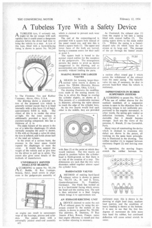
A TUBELESS tyre, if seriously cut, /-i might let the air escape with such rapidity that it could create a dangerous situation before the driver had time to bring the vehicle to a stop. A tyre of this type, fitted with a burst-delaying lining, is shown in patent No. 701,240
by The Firestone Tire and Rubber Company, Akron, Ohio, U.S.A.
The drawing shows a pictorial section of the proposed tyre which is generally normal except that it is lined internally with a thin layer (1) of butyl,
approximately 0.010 in. thick. The object of this is to render the cover air-tight. On the inner surface is additionally provided a layer (2) of puncture-sealing compound; this has a thickness of 156 in.
The main feature of the patent is the use of a tube-like diaphragm (3) which nbrmally occupies the posit'^n shown. It fills with air through a valve (4) when the tyre is inflated, and holds about half of the total air volume.
In the event of a serious burst, the pressure in the inner space would expand the diaphragm to meet the cover. It would thus support the weight of the vehicle and so give time for the driver to pull up in safety. The Patent also gives some details of the methods of manufacture.
UNIVERSALLY JOINTED SMALL-END BEARING A CCORDING to patent No. 701,194 IA (C. Bodda, 10 Rue Luzzago, Brescia, Italy), small errors in alignment in the gudgeon-pin assembly of an engine can result in unnecessary wear of the bearings, pistons and cylin ders. The patent deals with a universally jointed small-end assembly 832 which is claimed to prevent such wear occurring.
The end of the connecting-rod is provided with a square hole instead of the usual round one, and into this is fitted a square bush (1). The upper and lower faces of the bush are 'curved, having a common centre for their radii at point 2.
The square bush is bored to the normal round outline for the reception of the gudgeon-pin. The arrangement permits the piston to pivot as shown exaggerated in the drawing, and so accommodate any slight inaccuracies of assembly without loading the parts.
• MAKING ROOM FOR LARGER VALVES
AMEANS for housing larger-thannormal valve inserts is shown in patent No. 700,846 (Hercules Motors Corporation, Canton, Ohio, U.S.A.).
The drawing illustrates the modifications made to the seating inserts (1). One is to allow the flange to overlap the cylinder slightly, as shown at 2. This permits of a considerable increase in diameter, allowing the valve almost to reach the edge of the cylinder bore. As the two inserts would foul each other in the middle, they are provided with flats (3) at the point at which they would intersect. The two inserts are placed in position before the cylinderhead is finish-ground, so that there is no risk of the creation of a step. The dimensions are such that the two valve diameters added together almost equal the cylinder bore.
HARD-FACED VALVES AMETHOD of making hard .faced exhaust valves is shown in patent No. 701,753 (A., H. and E. Teves, Gustavsburgstrasse 31, Frankfurt, Germany). The blank has welded on to it a hard-metal facing which covers the head and the seating area. rhe unit is then subjected to a final forging which brings it to approximate size.
AN EXHAUST-EJECTING UNIT
ADEVICE claimed to assist the exit of exhaust gases by using the airstream created by the motion of the vehicle, is shown in patent No. 701,260. The patentee, R. Damiens, 55 Rue Jeanne d'Are, Rouen, France, states that engine efficiency is raised and that no further silencing is necessary.
As illustrated, the exhaust pipe (1) from the engine is led into a casing fitted with conical baffles (2). The casing tapers down to the main outlet
(3). Within the casing is a funnelshaped tube (4) which faces the air stream at its large end. The passage of the air through the funnel creates suction effect round gap 5 which assists the withdrawal of the exhaust from the outer casing. The butterfly valve (6) can, if necessary, be shut to prevent back-flow when the vehicle is stationary.
IMPROVEMENTS IN RUBBER SUSPENSION SYSTEMS
A CCORDING to patent No. 702,417, tithe use of rubber sleeves for the resilient members of a suspension system is open to the objection that the restoring torque is not uniformly proportional to the angular movement; in other words, the spring gets weaker as deflection increases, whereas it is desirable that it should become stronger. Such are the views of the patentee, C. Brandt, 23 rue Cavendish, Paris.
Many ways of constructing the device which is claimed to overcome this defect are shown in the patent, all working on the same basic principle; this is illustrated in the drawing. The rubber member (1) is trapped between stationary fingers (2) and moving ones (3).
In operation, the moving fingers stretch the rubber between the
stationary ones; this is shown in the drawing at slight load (top), medium load (centre), and the condition of heavy loading is shown at the bottom. It is easy to see that the first few degrees of movement do little more than bend the rubber, but continued deflection will cause actual stretch to occur.