


Suction-assisted Hydraulic Brakes
Page 62
If you've noticed an error in this article please click here to report it so we can fix it.
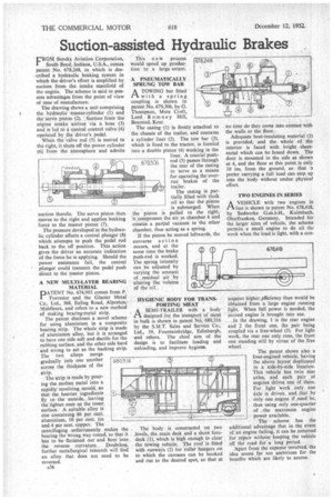
• CROM Bendix Aviation Corporation, I .South Bend, Indiana, U.S.A., comes patent No. 678,248, in which is described a hydraulic braking system in which the driver's effort is amplified by suction from the. intake manifold of the engine. The scheme is said to possess advantages from the point of view of ease of manufacture.
The drawing shows a unit comprising the hydraulic master-cylinder (1) and the'servb Piston (2). :Suction from the engine intake arrives via a hose (3) and is led t6 a central control valve (4) operated by the driver's pedal.
When the valve rod (5) is moved to the right, it shuts off the power cylinder (6). from the atmosphere and admits suction thereto. The servo piston then moves to the right and applies braking force to the master piston (7).
The pressure developed in the hydraulic cylinder affects a central plunger (8) which attempts to push the pedal rod back to the off position. This action gives the driver an accurate indication of the force he is applying. Should the power assistance fail, the central plunger could transmit the pedal push direct to the master piston.
A NEW MULTI-LAYER BEARING MATERIAL
DATENT No. 674,903 comes from P.
Forrester and the Glacier Metal Co., Ltd., 368, Ealing Road, Alpertow Middlesex, and refers to a new method of making bearing-metal strip.
The patent discloses a novel scheme for using aluminium in a composite bearing strip. The whole strip is made of aluminium alloy, but it is arranged to have one side soft and ductile for the rubbing surface, and the other side hard and strong to act as the backing strip. The two alloys merge gradually into one another across the thickness of the strip.
. The strip is made by pouring the molten metal into a rapidly revolving mould, so that the heavier ingredients fly to the outside, leaving the lighter, ones on the inner, surface.A suitable alloy is one•containing 86 per cent. aluminium, 10 per cent. tin and 4 per cent. copper. The
centrifuging .unfortunately makes the bearing the wrong way round, so that it has to be flattened out and bent into the reverse curvatnre. Doubtless, further metallurgical research will find an alloy that does not need to be reversed.
A36 This n e w process would speed up production to a large extent.
A PNEUMATICALLY SPRUNG TOW BAR
A TOWING bar fitted 1"3. with a spring coupling is shown in patent No. 679,306, by G. Thompson, Mote Croft, Lord Romney Hill, Bearsted, Kent.
The casing (1) is &tidy attached to the chassis of the trailer, and contains a cylinder liner (2). The tow bar (3), which is fixed to the tractor, is formed into a double piston (4) Working in the liner. A coaxial pushrod (5) passes through the rear of the casing to serve as a means for operating the overrun brakes of the trailer.
The easing is partially filled with thick oil so that the piston is submerged. When the piston is pulled to the right, it compresses, the air in chamber 6 and creates a partial vacuum in the other chamber, thus acting as a spring.
If the piston be moved leftwards, the converse action occurs, and at the same time the brake push-rod is worked.
The spring intensity can be adjusted by
varying the amount of . residual air by altering the volume : of the oil._ HYGIENIC BODY FOR TATSPORTING MEAT A'. SEMI-TRAILERwith a' body designedfor the transport of meat in bulk is shown in patent NO. 680,316 by the S.M.T. Sales arid Service Co., Ltd., 39, Fountainbridge, Edinburgh, and others. The chief aim of the design is to facilitate loading and unloading, and improve hygiene.
The body is constructed on two _levels, the main deck and a short foredeck (1), which is high enough to clear the towing vehicle. The roof is fitted with runways (2) for roller hangers on to which the carcases can be hooked and run to the desired spot, so that at no time do they come into contact with the walls or the floor.
Adequate heat-insulating material (3) is provided, and the whole of _the interior is faced with bright sheetmetal which can be hosed down. The door is mounted in the side as shown at 4, and the floor at this point is only 10 ins, from the ground, so that -a porter carrying a full load can step up into the body without undue physical effort.
TWO ENGINES IN SERIES
AVEHICLE with two engines in line is shown in patent No. 678,418, by Sudwerke G.m.b.H., Kulmbach, Oberfranken, Germany. Intended for the larger sizes of vehicle, the scheme permits a small engine to do all the work when the load is light, with a con
sequent higher efficiency than would be obtained from a large engine running light. When full power is needed, the second engine is brought into use.
In the drawing, I is the rear engine and 2 the front one, the pair being coupled via a free-wheel (3). For light work, the rear one only runs, the front one standing still by virtue of the free wheel.
The patent shows also a four-engined vehicle, hiving the above layout duplicated in a side-by-side location. This vehicle has twin rear axles, and each pair of engines drives one of them. For light work only one axle is driven, and that_by only one engine if rifted be, thus using only one-quarter of the maximum engine power available.
The scheme has the additional advantage that in the event of an engine failing, it can be removed 'for repair without keeping the vehicle off the road for a long period. • Apart from the expense involved, the idea seems far too ambitious for the benefits which are likely to accrue.