


A Rubber-bushed Shackle for Heavy Vehicles
Page 54
If you've noticed an error in this article please click here to report it so we can fix it.
D UBBER -.MOUNTED siding ends Pt are becoming increasingly popular for light vehicles, but they. have not proved tobe so satisfactory when subjected to the heaVierjoading of . buses and the like. A.-design-more suited to the latter type of 'vehicle' forms the sub-. ject of patent -No. 590,537,-froiri the Associated Equipment. Co., ; Ltd., ,G. Rackhani, and C. Stock, 211 of Southall,
Middlesex.
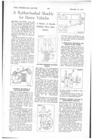
The .patent describes, the scheme as applied to both. the front and, the rear springs, and the drawing illustrates the latter. The spring-eye seats_ in a semicircular bush (1) which comprises metal inner and outer 'sleeves with a' bonded rubber intermediary. This being a movable shackle the same arrangement is duplicated above, and seats on a replica (2) of the. spring-eye formed on a frame bracket. Central pins are fitted to both units to -prevent side movement.
The flexing of the rubber is sufficient to accommodate. all normal deflection, which is about 25 degrees maximum under a preSstireof 600 lb. per sq: in. Any deflection -in excess of the above angle Would be Stopped by 'metal-tometal contact.
AVOIDING HOT-SPOTS IN AIR-COOLED ENGINES
inNE a the chief difficulties in the 14--/ design of air-cooled engines is the avoidance of hot-spots created by the shrouding of the fins by adjacent parts. This is particularly the case with overhead-valve engines, in which the valve gear may often obstruct the air flow. A valve layout intended to prevent this is shown in patent No. 591,158, by J. Jameson, Chessington Lodge, Spring Street, Ewell, Surrey..
The . drawing shows a view of one cylinder of a multi-cylhiclered engine: The overhead-valve arrangements are such that a" tunnel" (l). is left across. the cylinder -head to permit a free now : of air to the hottest region.. The, two valves, one of which is shown (2)„are located one on the upper side and the second on the lower, but both operating rods run together on the -upper. side„ does also the induction pipe.
The Valves are worked by wire Table pull-rods (3) instead of the usual push variety. This means that much smaller rods can be used, saving weight and affording less obstruction to the air flow.
A36 SUCTION-MODIFIED IGNITION TIMING
AN adjunct to the usual speed-controlled ignition timer is shown in patent No. 590,512, by Joseph Lucas, Ltd., and others, Great King Street, Birmingham The proposed device is 'a suction-operated diaphragm responding to the conditions in thern induction , manifold.
It is ilesired that the Spark shall be retarded when the suction is'greatest (during idling), advanced when the suction falls, but retarded again when the suction falls below a certain pre-determined value, This action is produced in the following manner; A diaphragm in' the casing (1) moves a liak (2) which is pivoted to a short lever (3) rocking on the housing and a longer fever (4) pivoted on the contact-breaker assembly.
When thediaphragm moves upwardly, the contact-breaker is first rocked clockwise until the levers reach their in-line position, after which further diaphragm movement reverses the direction of rocking. The patent covers the principle involved; other methods of achieving it are also shown.
A HIGH-LEVEL DRAWBAR FOR AGRICULTURAL WORK
AN increased degree of manceuvrability is the main object of a tractortrailer drawbar shown inpatent No. 590,979, by Roadless Traction, Ltd., P. Johnson, and L. Tripp, all of Gunnersbury Honse, Hounslow, Middlesex.
The drawiag shows the scheme reduced to its simplest possible terms. A tracklayer (1) is coupled to an implement (2) by means of the high-level drawbar (3). The bar is pivoted on both the tractor and the implement, so that it is possible to run with the implement offset. This feature is particularly use ful when working in orchards or other obstructed spaces.
The drawbar acts also as a torque rod to resist the forces tending to overturn the tractor in a backwards direction.
TRAPPING FOREIGN MATTER IN CRANKSHAFT OELWAYS
PATENT No. 590,977 comes from the Ford Motor Co., Ltd., 88, Regent Street, London, W.1, and describes a method. of isolating impurities in engine oil. The scheme is aimed at trapping the metallic particles as they flow through the oilways of the crankshaft. . In the interior of, each crankpin the oilway is,eniarged as at 1.The action -depends on the fact that nietal particles, being inuch heavier than ,the oil, will be thrownto the largest radius of revolution, whilst the bearing passages (2) are led from the smallest radius. ,
In operation, impurities will collect in the vicinity of plug 3, whence they can
• be removed as a routine operation. To facilitate cleaning, the bore may be lined with a thin metal cartridge, which, when removed, brings away the collected matter with it,