


Grading Valve for Air Braking
Page 36
If you've noticed an error in this article please click here to report it so we can fix it.
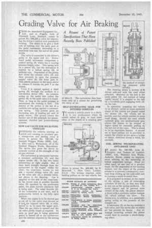
CROM the Associated Equipment Co., Ltd., and A. Prifildle, both of Windmill Lane, Southall, comes in patent No. 540,145 a valve for improving the driver's control over pneumatic braking. The object is to give a slow rate of braking over the early part of the pedal movement, increasing to a maximum rate near the end of the pedal stroke.
The valve is connected to the driver's pedal at the upper end (1). Downward pedal movement compresses a conical spring (9) which has a varying pressure-length ratio. This spring acts on a piston (2), but the movement is resisted by a helical spring (4) of uniform rate. Depression of the piston first closes the exhaust valve (3) and then proceeds to open the pressure supply valve (5) fed from port 8. This admits pressure to the space above it, whence it travels via port 7 to the brakes.
Valve 5 is opened against a third spring (6) through the medium of a lost-motion device (10). Air pressure acting on the under side causes the piston (2) to lift until valve 5 is closed. Thus, so long as the pedal pressure is maintained the braking is held. The essence of the patent is the use of a variable-rate spring against a constant
rate spring. This scheme gives an increasing rate of braking per unit of pedal travel. The patent covers the further use of the principle for poweroperated clutches and power-steering systems.
NEW GAS VALVE FOR SOLID-FUEL VEHICLES I NTENDED for vehicles starting on petrol and running on producer gas, a change-over and mixing valve is shown in patent No. 540,140, by Sentinel Waggon Works (1936), Ltd., S. Alley and L. Richardson; all of the Sentinel Waggon Works, Shrewsbury. The device also gives the driver an accurate control of the strength of the air-gas mixture.
The instrument is interposed between a standard carburetter (1) and the engine intake (4). It has two bores intersecting at right angles. One of these leads straight through from the carburetter to the engine, whilst the other, the cross-bore, houses on one side a tapered sliding valve (6), and on the other side (3) a throttle valve, not shown in the drawing. Gas is supplied to this side of the cross-bore. In the lowest tube is another throttle valve (5) operated by the accelerator pedal, the main control whichever fuel is being uSed. The usual throttle (2) of the carburetter is not used, and is permanently locked in the fully open position.
When the engine is to be started gas is cut off by the valve (not shown) at 3 and the tapered valve (6) is withdrawn so as to open the upper port. Then the gas valve is opened and the air valve partly closed as required. So soon as good gas is being generated petrol is turned off at the carburetter and the mixture, adjusted by the setting of vialve 6, The carburetter then functions only as a means for permitting the entry of air.
SELF-EXTRICATING GEAR FOR DITCHED VEHICLES
TO enable a vehicle stuck in a ditch, or in any predicament where its wheels refuse to grip, to haul itself clear, is the object of a winding gear
shown in patent No. 539,962, by D. Moncrieff, I, Hare Court, London, E.C.4. The scheme employs cablehauling pulleys on the rear wheels, but the method of mounting possesses some novelty.
The drawing shows a section of 4a driven axle-end with the road wheel attached. Mounted on the hub is the cable pulley (2), but instead of being rigidly keyed, it is coupled to the hub by a reversible pawl engaging teeth (3) on the hub.
In operation, assuming the vehicle to be ditched, cables or ropes anchored ahead of the vehicle are passed round the drums (2), the wheels set in motion, and the vehicle enabled to warp itself along. Should the road wheels suddenly grip, the unidirectional gear allows the drums to be rotated at higher speed by manually pulling on the tail end of the ropes. This is stated to be an important feature. A second set of fixed pulleys (1) is provided to enable the vehicle to run upon a bridge of cables, stretched across a ditch, 'for example.
COIL SPRING INCORPORATING ANTI-SHOCK UNIT patent No. 540,192, from H. Doughty and Taskers of Andover (1932), Ltd., Waterloo Iron Works. Andover, Hants, comes an improvement relating to the mounting of helical suspension springs. These are often used, at one end of a pivoted beam, for the suspension of low-loading trailers, and the object of the present scheme is to prevent a momentary overload from closing up the coils solid and so causing a metal-to-metal blow.
It is proposed to mount, in the centre of the spring, a pair of telescoping cylinders (2 and 3), so that they slide in and out as the spring oscillates. To avoid impact and to prevent total closure of the coils,, the piston member is fitted with a synthetic rubber bumper (4) which softens the blow. The device acts, in addition, as a pneumatic spring owing to the presence of the trapped air.
A lubricator (1) at the top contains a ball valve, and this serves also to admit air but prevent its escape. Any air leakage occurring around the piston would tend to exercise a shock-damping effect.