


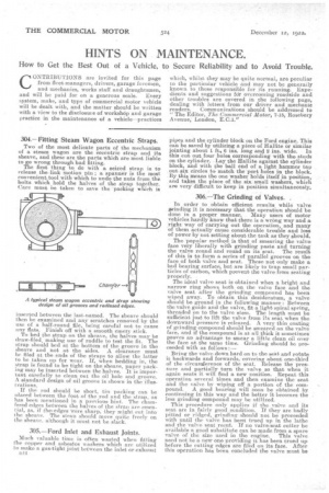
304. — Fitting Steam Wagon Eccentric Straps.
Page 28
Page 29
If you've noticed an error in this article please click here to report it so we can fix it.
Two of the most delicate parts of the mechanism of a steam wagon are the eccentric strap and its sheave, and these are the parts which are most liable to go wrong through bad fitting. The first thing to do With a seized strap is to release the link motion pin a spanner is the most convenient.tool with which to undo the nuts from the bolts which hold the halves of the strap together. Care must be taken to save the 'packing which is inserted between the last-named. The sheave should then he examined and any scratches removed by the use of a half-round file, being careful not to cause any flats„ Finish off with a smooth emery stick. To bed the strap on the shease, the halves may be draw-filed, making use of raddle to test the fit. The strap should bed at the bottom of the groove in the sheave and not at the sides. A clearance must be filed at the ends of the straps to allow, the latter to be taken up for wear. If, when bedding in, the strap is found to be tight on the sheave, paper packing may be inserted between the halves. It is important carefully to clean out the oil hole and groove. A standard design of oil groove is shown in the illustrations.
If the rod should be short, tin packing can be placed between the foot of the rod and the strap, as has been mentioned in a previous hint. The chamfered edges between the halves of the strap are essential, as, if the. edges were sharp, they might cut into the sheave. The strap should move quite freely on the sheave, although it must not be slack.
305.—Ford Inlet and Exhaust Joints.
Much valuable time is often wasted when fitting the copper and asbestos washers which are utilized to make a gas-tight joint between the inlet or exhaust n44
pipes and the cylinder block on the Ford engine. This can be saved by utilizing a piece of Hallite or similar jointing about 1 ft s 6 ins, long and 2 ins. wide. In this cut out four holes corresponding -with the studs on the cylinder. Lay the Henke against the cylinder block, and with the ball end of a light hammer tap out six circles to match the port holes in the block. . By this means the one washer holds itself in position, and takes the place of the six small washers, which are very'difficult to keep in position simultaneously.
306.—The Grinding of Valves. .
In order to obtain efficient results while valve grinding it is necessary that the operation should be done in a proper manner. Many users of motor vehicles hardly know that there is a wrong way and a right way of carrying out the operation, and many of them actually cause considerable trouble and loss of power by not setting about the task as they should.
The popular method is that of smearing the valve face very liberally with grinding paste and turning the valve round and round on its seat. The result of this is to form a series-of parallel grooves on the face of both valve and peat. These not only make a had bearing surface, but. are likely to trap small particles of carbon, which prevent the valve from seating properly.
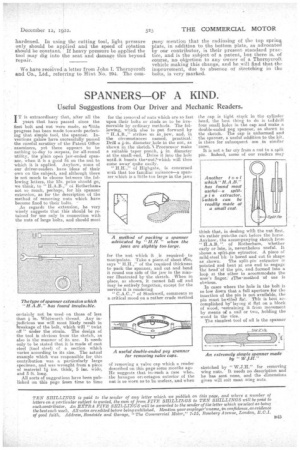
The ideal valve seat is obtained when a bright and narrow ring shows both on the valve face and the valve seat after the grinding compound has been wiped away. To obtain this desideratum, a valve should be ground in the following manner : Between the valve guide and the valve, fit a light spiral spring, threaded on to the valve stem. The length must be sufficient just to lift the valve from its seat when the downward pressure is released. A very thin coating of grinding compound should be smeared on the valve face, and if the compound is at all thick it sometimes proves an advantage to smear a little clean oil over the face at the same time. Grinding should be proceeded with as follows :— Bring the valve down hard on to the seat and rotate it backwards and forwards,covering about one-third of the circumference of the seat. Release the pressure and partially turn the valve so that when it again seats it will find a new position. Repeat this operation several times and then examine the seat and the valve by wiping off a portion of the compound. A good bearing will soon be obtained by continuing in this way and the better it becomes the less grinding compound may be utilized.
This procedure only applies if the valve and its seat are in fairly good condition. If they are badly pitted or ridged, grinding should not be proceeded with until the valve has beau trued up in the lathe and the valve seat recut. If no valve-seat cutter be available a good substitute can be made from a spare valve of the size used in the engine. This valve need not be a new one providing it has been trued up before the cutting edges are filed on its face. After this operation has been concluded the valve must be
hardened. In using the cutting tool, light pressure only should be applied and the speed of rotation should be constant. If heavy pressure be applied the tool may dig into the seat and damage this beyond repair.
We have received a letter from John I. Thornyeroft and Co., Ltd., referring to Hint No. 294. The corn puny mention that the radiusing of the top spring plate, in addition to the bottom plate, as advocated .by our contributor, is their present standard practice, and is the subject of a patent, but there is, of course, no objpction to any owner of a Thornycroft vehicle making this change, and he will find that the improvement, due to absence of stretching in the bolts, ist very marked.