


A HIGH-PRESSURE LUBRICATINGSYSTEM.
Page 66
If you've noticed an error in this article please click here to report it so we can fix it.
A Résumé of Recently Published Patent Specifications.
TECALEMIT, LTD., in its specification No. 228,905, describes a somewhat new feature in a system of introducing lubricant under very high pressure. The specification points out the great difficulty that has been experienced in preventing leakage from a flexible tube containing lubricant when a very high pressure is exerted to drive the lubricant into the parts where it is needed. Flexible tubes In such circumstances may not leak when new, but, owing to the rough handling they get in an oidinary garage, and to their constantly being bent in all directions, they usually develop leaks sooner or later.
The present invention aims at remedying this defect, and at the same time provides a means whereby a portable container and a long flexible lead may be employed without fear of undue leakage. The apparatus consists of a container provided with a piston, or pump, which will provide just sufficient pressure on the bulk of the lubricant to drive it along a conveniently long pipe leading to a special grease gun with a suitable means for attaching, its nozzle to the point where lubrication is needed. The low pressure in the main cylinder is just sufficient to fill the gun, whilst the small area of the piston of the latter enables an operator to force the lubricant into any desired part with great pressure.
A Power-increasing Machine.
A VERY wonderful and revolutionary "invention" is -`.• described in the specifidation of Karel Clabots, of Brussels, No. 266,444. The modesty of the "inventor," however, prevents him from claiming to have discovered perpetual motion, so he contents himself by describing it in the following terms:—
" This invention relates to a power-increasing machine, i.e., to a machine in which power axplied by an electric motor or other prime mover is increased and can be used to do more work than the prime mover itself is capable of doing or can be used in part to supply power to drive the motor or other prime mover, the surplus power being employed to do useful work."
Many such "inventions" figure in the list of patents during the year, but to the credit of British mentality we are glad to say that in nearly all cases they hail from abroad.
A Built-up Crankshaft.
MANY attempts have been made from tithe to time to in
troduce a built-up crankshaft for the engines of automobiles, but up to now the one-piece crank appears to hold its own against all efforts to supplant it. The specification of P. H. Royce, No. 266,08, describes a crank in which the webs near to certain of the main bearings are formed with screwed holes to receive the threaded pins that project and are integral with the webs of the adjacent throws. The crank constructed according to this invention is made up of alternate parts, consisting of a main bearing, formed integral with one or two webs, according to its position, and Projecting pins that are screwed into holes in other webs and then held by means of clamping bolts.
We consider that we have s,en other attempts to design a built-up crank which we believe are more promising. . In the present design we think we can see difficulty in locating the positions of the main journals so that they mate with the bearings in the crankcase, owing to the lengthwise measurements of the crank being determined entirely by screw threads, a partial turn, more or less, of which to bring the throws in line would alter the length. Another point that strikes us is the danger of fracture that may arise from the thread cut in the crank pin, as designers have found that the slightest sharp corner, is likely to start a fracture, hence the care taken to form a bold radius at all junctions of the pin and web.
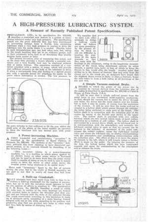
A Simple Vacuum-assisted Brake. A BRAKE in which the power of the driver can be assisted by vacuum derived from the induction pipe of the engine is described in specification No. 250,195 of Caleb S. Bragg, of Palm Beach, U.S.A.
It will be seen that a simple pull-rod passes from the pedal lever to any convenient brake-applying mechanism, so that, should the vacuum fail to assist the driver through any cause, the driver has the usual control over his brakes, but in such a case he would, of course, lose the. assistance of the vacuum. It will be seen that the brake pull-rod is coupled to a hollow shaft which passes through the cylinder, the latter being anchored to some part of the frame. The hollow shaft is in connection with the induction pipe of the engine by means of the flexible pipe shown in the upper view. The hollow shaft is provided with two collars, between which are two conical valves made of hard rubber, separated by a cushion of soft rubber. The hollow shaft is surrounded by a second sleeve Which,. at its left-hand end, is in communication with the atmosphere, and normally the left-hand conical valve is open so that no vacuum can be induced in the cylinder. A movement of the pedal compresses the rubber cushion, opens the -right-hand conical valve and closes the left-hand one, so closing communication with the atmosphere and establishing communication with the induction pipe. The effect of this is to move the piston by vacuum to the left, where it will remain unless a further effort is made on the pedal. On relaxing the pressure of the foot, the helical spring which has been compressed expands and opens the communication to the atmosphere and so releases the brake.