


DISPLACING THE CLUTCH AND GEARBOX.
Page 57
Page 58
If you've noticed an error in this article please click here to report it so we can fix it.
Another Attempt to Produce an Infinitely Variable Gear. An Interesting Device Still in its Experimental Stage.
THE advantages of an infinitely variable gear ratio between the enene and the rear wheel are too well known to need amplification, but up to the present only a few pioneer inventors have produced schemes that are really workable. A very promising device has been invented and patented jointly by Mr. E. E. Guinness and Mr. A. E. Jones, of Wolverhampton. The gear appears to be comparatively cheap to manufacture, compact and light in weight—features which are essential in order to produce a popular successor to the conventional type of gearbox.
Although only just reaching the stage where " the proof of the pudding" can really be ascertained, the basic principle of the invention has been tested out under actual road conditions in a car some time ago. As migbt be expected with a first attempt, the gear did not work so satisfactorily as it might, but many valuable lessons were learnt, and a new and improved type—using the same idea—hasrecently been built
and will shortly be mounted in a chassis for test purposes. The original gear—we understand—gave very good results considering the fact that it was entirely hand-made. The-new edition, however, has not only been improved in design but all parts are more soundly constructed, and everything indicates that, if the old gear worked, the new one should work very much better.
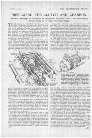
The whole of the variable gear is housed within an aluminium casting bolted direct to the engine, and it provides the necessary mechanism to dispense with the clutch as well as the gearbox. A propeller shaft is used in the ordinary way, together with the usual reduction gear in the rear axle; thus it will be seen that existing vehicles can be converted from a three or fourspeed type to the infinitely variable type when the device has been perfected.
The basic principle of the invention aims at converting the continuous rotating movement of the engine into an oscillating movement, which by a variation of the amplitude of the oscillations (by a control) can be reconverted to a continuous rotating movement, the speed of the latter being capable of variation from that of the engine. In effect, two stages are therefore necessary, the first to produce the oscillating movement, which, of course, must be variable, and, secondly, to convert this oscillating movement to a rotary movement again. Dealing first with the means for obtaining the variable gear. A shaft with its.centre line set obliquely to the centre line of the crankshaft is attached direct to the enaine fly Wheel in such a manner that.the centreline of the shaft crosses the centre line of the crankshaft. Thus, when the. engine revolves there is a point on the oblique shaft which has no movement at all, i.e., at the intersection eof the two centre lines ; the centre line of the shaft itself actually describes a conical path.. A phosphor-bronze truncated ball is arranged to slide on this oblique shaft, the ball carrying the housing which really takes the form of a connecting-rod assembly similar to that used in a radial aero engine.
It will be seen by reference to one of the diagrams that, as the ball, complete with its connecting rod assembly, is moved along the oblique shaft, a rotary movement (which varies according to the position of the connecting rod) is given to the big-end of the connecting rod. Thus, if the centre line of the truncated ball coincides with the centre lines of the crankshaft and the oblique shaft, no rotary movement whatever will be given to the ball, whilst if it be at the far end of the shaft—nearest the flywheel—the rotary movement will be at its maximum. So far, we have arrived at the position where a given rotary movement which can be controlled in diameter is given to a unit comprising a series of three connecting rods.
Turning for a moment to the layout of other, parts of the box. Ranged radially around the oblique shaft are further shafts with throws (which, for convenience, we will call ordinary crankshafts), each shaft being attached to the connecting-rod unit by short links with pin joints at both ends, except on one link which forms a master connecting rod. In this way the varying -rotary movement provided by the oblique shaft is transmitted to each of the three crankshafts, which in turn oscillate in direct proportion to the rotary movement of the big-end of the connecting rod.
The conversion from the oscillating movement to the rotary movement is effected by arms attached to the .ends of the three crankshafts to which links are fitted which connect to a one-way-drive arrangement. It will be seen then, that, as the crankshaft oscillates to a varying degree, so the links transfer the oscillatory movement to the one-way drive, the amplitudes of the driving members (in the one-way drive) being in direct proportion to the amplitudes of the crankshafts. The motion given to the driven member (of the oneway drive) is transferred through the medium of a dog Clutch to the propeller shaft, thence to thk. driving wheels. The one-way drive is actual1l in three parts, each part being connected to one of the crankshafts, so that for each revolution of the engine three impulses (with three crankshafts) are given to the propeller shaft, the number of impulses given to the rear wheels being increased according to the rear-axle finaldrive ratio. As the driving member of the one-waydrive device oscillates, movement is given to the driven (internal) member by a roller and ratchet arrangement which, if accurately constructed, causes very little lost motion in the drive.
In order to provide a direct drive between the engine and the propeller shaft—corresponding to top gear on the conventional type of box—a sleeve is arranged so that it slides on the tail shaft of the gearbox which is attached direct to the propeller shaft. When this is connected the gear can, by means of a suitable control, be moved into the neutral position, i.e., at the intersection of the oblique shaft and crankshaft centre lines, the only motion in the gear itself then taking place being the semi-rotary motion of the truncated ball within the housing of the connecting-rod assembly.
When a gradient is reached by the vehicle and a lower gear than that provided by the direct ratio is required, the gear can be brought up to the top position (i.e., the connecting-rod assembly moved along the oblique shaft), the direct-drive dog clutch disengaged and the drive for the infinitely variable gear engaged in its place, after which the position of the connectingrod assembly on the oblique shaft can be altered (and consequently the gear ratio) at will to suit the special conditions of either load or gradient.
We have had an opportunity of inspecting the gear while it was being motored round from .a workshop lathe, which gave us an excellent opportunity of trying the various positions for the connecting-rod assembly on the oblique shaft. The gear undoubtedly worked very well indeed, but, of course, the load which was being transmitted was practically negligible. We await. further developments with interest and will deal with them in this journal.