


With Intent to Improve.
Page 22
If you've noticed an error in this article please click here to report it so we can fix it.
A Weekly Summary of Recent Patents, of Interest to the Maker and User of Commercial Motor Vehicles.
Selected and Abridged by H. S. Hall, A.M.I.A.E.
A Carburetter Improvement.
Brown and Barlow? Ltd., of Westwood Road, Witton, Birmingham, in specification No. ;03,872, describes an improvement in coanection with carburetters. This invention is applicable mainly to carbtfretWrs of the type involving a sub-, merged jet. In this type of carburetter, it is customary to incorporate an air con-duit,communicatiog with a fuel passage above the jet but below the norinal level of the supplysluel. This air conduit is suitably -.restricted so that it does not have the effect of entirely relieving the jet' from the influence of the suetion. A feathre of this type of carburetter is that is fine adjustment of the amount of fuel
leaving the primary jet can be effected by regulating the size of this air conduit.
It is in connection with -this adjustment that the patent has been effected, in that, with the device described in, the specification—various forms are shown— the amount of adjustment is limited between two extremes. One extreme of adjustment allows maximum power being developed by the engine to which the carbitretter is fitted, irrespective of fuel consumption ; with the other extreme of this adjustment, the . maximum of eConomy is attained, lant without consideeation of power developed. Several means of attaining the end in view are described and illustrated. In the drawing we reprodnce, the air conduit in question is closed by a nipple;' this nipple is drilled and tapped axially at the end which enters the air conduit or passage leading to the jet. This tapped hole is in communication, through the upper part of the nipple,with the atmosphere, and it is almost closed by means of a small screwed plug. This plug has a transverse slot which reaches nearly to its lower extremity. A central hole is drilled in the plug at the end communicating with the bottom, edge of this transverse slot. It is by Ineads of this slotted plug that adjustment of the air admit1ed to the conduit is effected. In the position illustrated by our drawing, it will be observed that air can enter through the transverse slot, a small portion of which is exposed below the bottom of the nipple, and also through the drilled hole in the end of the plug. By screwing tie plug further into the nipple, the transverse slot can' be completely engulfed within the nipple, leaving only an air way through the small drilled' hole; this allows the minimum of air to enter. By unscrewing the plug, more and more of the transverse slot is exposed thus creasing the area for ingress of air. The limit of the amount of air that can enter. is set by the small bush, a little lower in the air conduit.
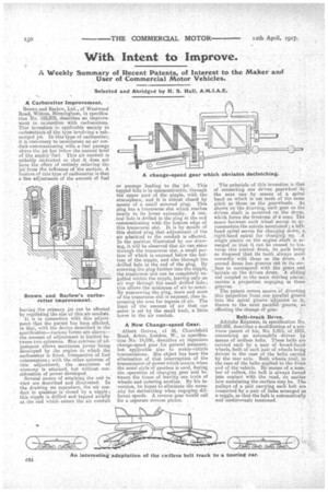
A New Change-speed Gear.
Albert Groves, of 96, Churchfield Road, Acton, London, W., in specification No. 14,036, describes an ingenious change-speed gear for general purposes, but applicable also to motor-vehicle transmissions. His object has -been the elimination of that interruption of the transmission of power which occurs, when the usual style 'of gearbox is used, during, the operation of changing gear and between the times of leaving one train of wheels and entering another. By his invention, be hopes to eliminate the necessityfor declutching when engaging different speeds. A reverse gear would call fOr a separate reverse pinion. .
The principle of this invention is that of connecting one driven gearwheel ,to the next one by -means of a spiral band on which is cut teeth of the same pitch as those on the gearwheels.. As shown on the drawing, each gear on the driven shaft is mounted on the drum, which forms the frustrum of a; cone. The space between each wheel serves to accommodatelthe spirals mentioned ; a lefthand spiral serves for changing down, a right-hand spiral for changing -up. A single pinion on the engine shaft is arranged so that it can be caused to traverse this conical drum its path being so disposed that its teeth always mash correctly" with those on the drum. second drum has grooves cut in its surface to correspond with the gears, and 'spirals on the driven drum. A sliding rod coupled to the main driving pinion, i carries a projection engaging n these grooves. , '
The patent covers means of diverting this projection from one parallel groove into the spiral groove -indjaceirt to it, thence to the next parallel groove, so effecting the change of gear.
Belt-track Drive,
Adolphe Kagresse, in specification No. 103,855, describes a modification of a previous patent of his, No. 5,015, of 1913, concerning an automplaile driven by" means of endless belts. These belts are carried each by a pair of broad-faced wheels, both of each pair of wheels being driven in the case ofthe belts carried by the rear axle. Both wheels trail,. in the case of the belts applied to the' front end of the vehicle. By means of a nu/11z her of rollers, the belt is always forced into contact with the road, no matter how undulating the surface may be. The pulleys of a pair carrying each belt are connected by a pair of links arranged 'as a toggle, so that the belt is automatically and continuously tensioned.