


AN AUTOMATIC CHANGE-SPEED GEAR.
Page 72
If you've noticed an error in this article please click here to report it so we can fix it.
A ,Resume of Recently Published Patent Specifications.
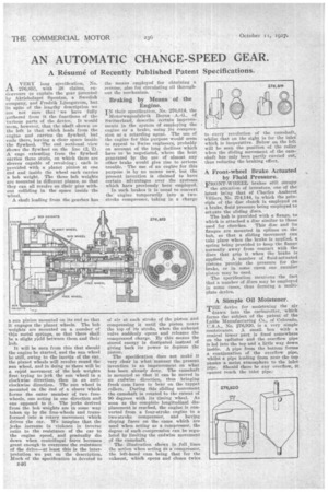
AVERY long specification; No. 276,857, with 38 claims, endeavours to explain the gear patentedby Aktiebolaget Spontan, a Swedish company, and Fredrik Ljungstrom, but In spite of the lengthy description we are not sure that • we have fully gathered from -it the functions of the various parts of the device. It would seem, however, that the shaft shown on the left is that which leads from the engine and carries the flywheel, but , ends there, leaving a clear space inside the flywheel. The end sectional view allows the flywheel on the line (2, 2). A cage extending from the flywheel carries three studs, on Which there are sleeves capable of revolving; each is provided with a planet pinion at one end and inside the wheel each carries a bob weight. The three bob weights are mounted in different planes, so that they can all revolve on their pins without colliding in the space inside the wheel.
A shaft leading from the gearbox has a sun pinion mounted on its end so that it engages the planet wheels. The bob weights are mounted on a number of thin metal springs, so that there shall be a slight yield between them and their hub.
It will be seen from this that should the engine be started, and the sun wheel be still, owing to the inertia of the car, the planet wheels will revolve round the sun wheel, and in doing so there will be a rabid movement of• the bob weights first trying to jerk the sun wheel in a clockwise direction, then in an anticlockwise direction. The sun wheel is mounted on the end of a sleeve which forms the outer member of two freewheels, one acting in one direction and one opposed to it. The jerks derived from the bob weights are in some way taken up by the free-wheels and transformed into a rotary movement which drives the car. We imagine that the jerks increase in violence in inverse ratio to the resistance of the car to the engine speed, and gradually die down when centrifugal force becomes great enough to overcome the resistance of the drive—at least this is the interpretation we put on the description. Much of the specification is devoted to
B46
the means employed for obtaining a reverse, also for circulating oil throughout the mechanism.
Braking by Means of the Engine.
IN their specification, No. 276,814, the Motorwagonfabrik Berne A.-G., of Switzerland, describe certain improve_ meats in the system of employing the engine as a brake, using its compression as a retarding agent. The use of the engine for this purpose would seem to appeal to Swiss engineers, probably on account of the long declines which have to be negotiated, where the heat generated by the use of almost any other brake would give rise to serious trouble. The use of an engine for this purpose is by no means new, but the present invention is claimed to have certain advantages over the systems which have previously been employed.
In such brakes it is usual to convert the engine temporarily into a twostroke compressor, taking in a charge of air at each stroke of the piston an I compressing it until the piston nears the top of its stroke, when the exhaust valve suddenly opens and releases the compressed charge. By this means the stored energy is dissipated instead of giving back its power to depress the piston.
The specification does not make it very clear in what manner the present invention is an improvement on what has been already done. The camshaft is mounted so that it can be moved in an endwise direction, thus bringing fresh cam faces to bear on the tappet rollers. During this sliding movement the camshaft is rotated to the extent of 90 degrees with its timing wheel. As soon as the complete longitudinal displacement is reached, the engine is converted from a four-stroke engine to a two-stroke compressor, and having sloping faces on the cams which are used when acting as a compressor, the degree of such compression can be regulated by limiting the endwise movement of the camshaft.
The illustration shows in full lines the action when acting as a'compressor, the left-hand cam being that for the exhaust, which opens and closes twice to every revolution of the camshaft, whilst that on the right is for the inlet which is inoperative. Below on the left will be seen the position of the roller when the sliding movement of the camshaft has only been partly carried out, thus reducing the-braking effect.
A Front-wheel Brake Actuated by Fluid Pressure.
FRONT-WHEEL brakes still occupy
the attention of inventors, one of thelatest being that of Charles Amherst Villiers, No. 274,144, in which the principle of the disc clutch is employed as a brake, fluid pressure being employed to actuate the sliding discs.
The hub is provided with a flange, to which is attached a disc similar to those
used for clutches. This disc and its flanges are mounted in splines on the hub, so that a sliding movement can take place when the brake is applied, a spring being"provided to keep the flange normally away from contact with the discs that grip it when the brake is
applied. A number of fluid-actuated pistons provide the pressure for the brake, or in some cases one annular piston may be used. The specification mentions the fact that a number of discs may he employed in some cases, thus forming a multiplate device,
A Simple Oil Moistener.
TnE device for moistening the air drawn into the carburetter, which forms the subject of the patent of the Labbe Manufacturing Co., of Colorado, -U.S.A., No. '476,920, is a very simple contrivance. A small, box with a conical lower part is fixed somewhere on the radiator and the overflow pipe is led into the top and a little way down inside. A pipe from the bottom forms a continuation of the overflow pipe, whilst a pipe leading from near the top passes a moist atmosphere to the inlet pipe. Should there be any overflow, it cannot reach the inlet pipe.