


A FREE-WHEEL IN THE TRANSMISSION LINE.
Page 54
Page 55
If you've noticed an error in this article please click here to report it so we can fix it.
The Humfrey-Sandberg Change -speed Device Interposed Between Gearbox and Propeller Shaft. Restarting a Dormant Engine.
a slipping device. We will, however, refer later to these items after fully describing the de.vice.
'VOL-LOWING upon the article on the subject of the 1: free-wheel in the line of the transmission which appeared in the issue of The Commercial Motor for September 13th, we decided to give as much detailed description as is available with regard to the leading principles of the various efforts that are being made at the present moment in the direction of introducing the device for private cars and commercial motors. With this object in view we gave in the issue for October 4th a description of the Joseph device, and this we now follow with a description of the HumfreySandberg free-wheel clutch at the rear of the gearbox.
This device consists mainly of a new form of freewheel or unidirectional drive. The invention may be applied in two ways. A separate clutch may be fitted to each pair of gears, all gears being in constant mesh, or it may be applied in the form Of a clatch situated behind the gearbox, and used as a free-wheel for coasting and as an aid to gear changing. It is With the latter application that we propose to deal here, as, on account of its simplicity, we consider this form to be more suitable for use on commercial vehicles, and it should be understood that in our remarks we are considering the device purely froth the point of. view Of the commercial vehicle where simplicity of mechanism and durability are essential factors.
By the courtesy 6f. Captain Irving (of 200-mile-perhour Sunbeam fame), who is chief engineer to the company which is developing the Humftey-Sandberg patents, we were given a most convincing road trial of two' private cars fitted with the device, and were enabled to make a careful examination of a set of rollers and cones which had been in use for a long period on a heavy vehicle, and we were also shown one of the free-wheels driven by an electric motor against the varying resistance of a dynamometer, thus demonstrating the manner of employing the clutch as B28
Description of the Clutch.
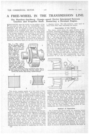
The clutch, which forms the main feature of the invention, somewhat resembles a Timken bearing, but, instead of taper rollers, parallel rollers are employed, and instead of the rollers being placed as in a Timken they are set at an angle to the axis, as shown in Fig. 1. The inner and outer members are not merely cones, but are formed to fit rollers set in a skewed position round a cone, or what might be described as
conoid, the shape of which can best be described by imagining two discs pierced with holes round their edge, and strings strained from one to the other, as shown on the left of Fig. 2. If such a structure had one Of its discs partly rotated, as shown on the right, the profile presented would represent the curves of the Inner and outer members if a sectionwere taken between the lines A-A and B-B. A roller if pressed between two surfaces will roll in a direction which is at right angles to its axis, consequently the rotary movement of one cone in relation to the other will
induce the inner member to wind its way into the outer member, whilst a reversal of the direction of rotation will have the effect of winding the two members apart.
This can only occur if the rollers are normally lightly pinched between the • inner and mite/ cone members of the free-wheel clutch, and this initial pressure is obtained by means of light springs exerting a pressure of approximately 30 lbs. If it is required to use the device as a slipping clutch it is only necessary to control the rate with which the inner member winds into the outer 'member. The method of controlling this rate Will be described later.
Method of Operation.
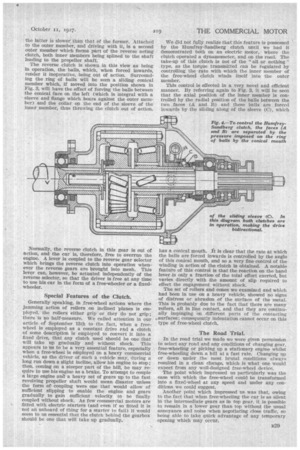
Fig. 4 shows the clutch ready for mounting behind the gearbox, and between it and the universal joint of the propeller shaft. The casing is intended to he bolted To the rear end of • a gearbox, and the shaft shown on the left is that which extends from the box, whilst the shaft on the right is intended to support the universal joint of the propeller shaft. Splined to the gearbox shaft Is the outer member_ of the forward driving clutch, which acts permanently as a forward drive and as a free-wheel by allowing, the propeller shaft to overrun the genr shaft whenever the speed of the latter is slower than that of the former. Attached to the outer member, and driving with it, Is a second outer member which forms part of the reverse acting clutch, both inner members being splined to the shaft leading to the propeller shaft. The reverse clutch is shown in this view as being in operation, the balls, which, when forced inwards, render it inoperative, being out of action. Surrounding the ring of balls will be seen a sliding conical member which, if moved into the position shown in Fig. 3, will have the effect of forcing the balls between the conical face on the left (which is integral with a sleeve and flange which bears against the outer member) and the collar on the end of the sleeve of the inner member, thus throwing the clutch out of action.
Normally, the reverse clutch in this gear is out of action, and the car is, therefore, free to overrun the engine. A lever is coupled to the reverse gear selector which brings the reverse clutch into operation whenever the reverse gears are brought into mesh. This lever can, however, be actuated independently of the reverse selector, so that the driver is free at any time to use his car in the form of a free-wheeler or a fixedwheeler.
Special Features of the Clutch.
Generally speaking, in free-wheel actions where the jamming action of rollers on inclined planes is employed, the rollers either grip or they do not grip; there is no half-measure. We called attention in our article of September 13th to the fact, when a freewheel is employed • as a constant drive end a clutch of some description is employed to convert it into a fixed drive, that any clutch used should be one that will take up gradually and without shock. This appears to us to be a very essential feature, especially when a free-wheel is employed on a heavy commercial vehicle, as the driver of such a vehicle may, during a long run down a slight incline, allow his engine to stop; then, coming on a steeper part of the hill, he may require to use his engine as a brake. To attempt to couple a large engine ana a heavy set of gears up to the fast revolving propeller shaft would mean disaster unless the form of coupling were one that would allow of sufficient slipping to enable the engine and gears gradually to gain sufficient velocity to be finally coupled without shock. As few commercial motors are fitted with electric starters (and even if so fitted it is not an unheard of thing for a starter to fail) it would seem to us essential that the clutch behind the gearbox should be one that will take up gradually. We did not fully realize that this feature is possessed by the Humfrey-Sandberg clutch until we had it demonstrated both on an electric motor, • where the clutch operated a dynamometer, and on the road. The take-up of this clutch is not of the "all or nothing" type, as the torque transmitted can be regulated by controlling the rate with which the inner member of the free-wheel clutch winds itself into the outer member. This control is effected in a very novel and efficient manner. By referring again to Fig. 3, it will be seen that the axial position of the inner member is controlled by the radial position of the balls between the two faces (A and B) and these balls are forced inwards by the sliding along of the sleeve (C), which has a conical mouth. It is clear that the rate at which the balls are forced inwards is controlled by the angle of this conical mouth, and so a very fine control of the winding in action of the clutch is obtained. A notable feature of this control is that the reaction on the hand lever is only a fraction of the total effort exerted, but varies directly with the amount of slip required to effect the engagement without shock. The set of rollers and cones we examined and which had been in use on a heavy vehicle, showed no signs of distress or abrasion of the surfaceof the metal. This is probably due to the fact that there are many rollers, all in line contact, and that they are continually impinging on different parts of the contacting ‘surfaces; consequently indentation cannot occur on this type of free-wheel clutch.
The Road Trial.
In the road trial we made we were given permission to select any road and any conditions of changing gear, free-wheeling or picking up a stationary engine whilst free-wheeling down a bill at a fast rate. Changing up or down under the most brutal conditions always resulted in a clean change, which is what one would expect from any well-designed free-wheel device. The point which impressed us particularly was the ease with which the free-wheel could be transformed into a fixed-wheel at any speed and under any conditions we could suggest. Another point which impressed us was that, owing to the fact that when free-wheeling the car is as silent in the intermediate gears as in top gear, it is possible to remain in a lower gear than top without the usual annoyance and noise when negotiating close traffic, so being able to take quick advantage of any temporary opening which may occur.