


MAKING BEST USE OF THE FORD.
Page 15
If you've noticed an error in this article please click here to report it so we can fix it.
Valuable Advice on Every Phase of Ford Transport, Which Will Appeal to the Owner, Driver and Repairer.
IN THIS series of hints concerning the Ford light chassis and ton truck wherever they are employed for commercial purposes, we endeavour to deal with the subject from every view-point, so that the advice given will appeal to the owner, driver, maintenance engineer or mechanic.
We shall welcome for inclusion among the hints those which have proved of value to individual users.
Readers are recommended to obtain the original " Book of the Ford," which constitutes a complete manual dealing with the Ford car, the van and the truck. 2s. 9d. post free from the offices of this journal. 254.—Facilitating the Replacement of Ford Bands.
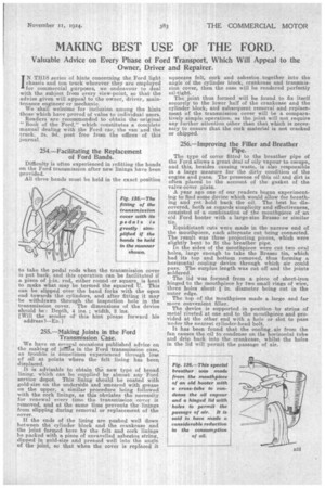
Difficulty is often experienced in refitting the bands on the Ford transmission after new linings have been provided.
All three bands must be held in the exact position to take the pedal rods when the transmission cover is put back and this operation can be facilitated if i a piece of -in. rod, either round or square, is bent to make what may be termed the squared U. This can be slipped over the band forks with the open end towards the cylinders, and after fitting it may be withdrawn through the inspection hole in the transmission cover. The dimensions of the device should be : Depth, 4 ins. ; width, 3 ins. (Will the sender of this hint please forward his address1--ED.1
255.—Making Joints in the Ford Transmission Case.
We have on sevesal occasions published advice on the making of jolhas in the Ford transmission case, as trouble. is sometimes experienced through loss of oil at points where the felt lining has been displaced.
It is advisable to obtain the new type of broad lining, which can be supplied by almost any Ford service depot. This lining should be coated with gold-size on the underside and smeared with grease on the upper, a similar procedure being followed• with the cork linings, as this obviates the necessity for renewal every time the transmission cover is removed, and at the same time prevents the linings from slipping during removal or replacement of the cover.
If the ends of the lining are pushed well down between the cylinder block and the crankcase and the joint formed here by the felt and cork linings be packed with a piece of unravelled asbestos string, dipped in gold-size and pressed well into the angle of the joint, so that when the cover is replaced it squeezes felt, cork and asbestos together into the angle of the cylinder block, crankcase and transmission cover, then the case will be rendered perfectly oil-tight. The joint thus formed will be found to fix itself securely to the lower half of the crankcase and the cylinder block, and subsequent removal and replacement of the transmission cover will be a comparatively simple operation, as the joint will not require any further attention other than that which is necessary to ensure that the cork material is not cracked or chipped.
256.—Improving the Filler and Breather Pipe.
The type of cover fitted to the breather pipe of the Ford allows a great deal of oily vapour to escape, and this, besides causing waste, is also responsible in a large measure for the dirty condition of the engine and pans. The presence of this oil and dirt is often placed to the account of the gasket of the valve-cover plate.
A year ago one of our readers began experiment-, ing to find some device which would allow for breathing and yet hold back the oil. The best he discovered, both as regards simplicity and effectiveness, consisted of a combination of the mouthpiece of an old Ford hooter with a large-size Brasso or similar tin.
Equidistant cuts were made in the narrow end of the mouthpiece, each alternate cut being connected. The result was three projecting pieces, which were slightly bent to fit the breather pipe. In the sides of the mouthpiece were cut two oval holes, large enough to take the Bra,sso tin, which had its top and bottom removed, thus forming a horizontal cooling device through which air could pass. The surplus length was cut off and the joints soldered.
The lid was formed from a piece of sheet-iron hinged to the mouthpiece by two small rings of wire, three holes about in, diameter being cut in the outer edge. The top of the mouthpiece made a large and far more convenient filler.
The device is supported in position by strips of metal riveted at one end to the mouthpiece and provided at the other end with a hole or slot to pass under the nearest cylinder-head bolt.
It has been found that the cooling_ air from the fan causes the oil to condense on the horizontal tube and drip back into the crankcase, whilst the holes in the lid will permit the passage of air.