


A FRONT-WHEEL DRIVE TRACTOR.
Page 28
If you've noticed an error in this article please click here to report it so we can fix it.
A Résumé of • Recently Published Patents.
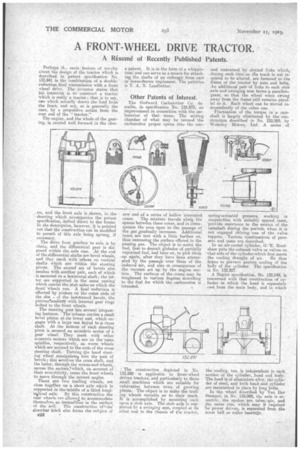
Perhaps -LI., main feature of »ovitti.' about the design of the tractor which is described in patent specification No. 132,841 is the combination of a doublereduction final transmission with a front _ wheel drive. The inventor states that his intention is to construct a tractor which is really a tractor ; that is to say, one which actually draws the load from the front, and not, as is generally the case; by a propulsive action from the rear end of the "tractor."
The engine, and the whole of the gearing, is carried well forward in the chas.
sis, and the front axle is shown, in the drawing which accompanies the patent specification, -bolted direct to the frame. in the description, however, it is pointed out that the construction can be modified to permit of this axle being sprung, if necessary. • The drive from gearbox to axle is by chain, and the differential gear is disposed within the axle ease. At. the end of the differential shafts are -bevel wheels, and they mesh with others on vertical shaft which are within the steering pivots. The second set of bevels also meshes with another pair, each of which • is mounted on a horizontal shaft ; the latter are supported in the same casting
which carries the stub axles on which the front-wheels run. A final reduction is • effected y pinions on the outer ends of the sha of the last.named bevels, the pinionstiteshurt with internal gear rings bolted to the front wheels.
The steering gear has several 'interesting features. The column carries a small bevel pinion at site lower end, which engages with a large one keyed to ;a. cross shaft. At the bottom of each steering pivot is secured an eccentric sector of a gear wheel. They mesh with other eccentric -sectors which are on the same spindles, respectively, as worm wheels which are secured to the ends of the cross steering shaft. Turning qie hand steerbig wheel roanipulateo. tirst the pair of bevels; this aevolves tile cross shaft, and the latter, through the worms and wheels, moves the sectors,lwhich, an account of their ecceatrieity, cause the front wheels to move through the Correct angles. There are tavo trailing wheels, set close together on a short axle which is supported in theuniddle of a third longi-. tuslinal axle. By this construction the rear wheels sre allowed, to accommodate thennetves so inequalities in the surface,
of the soil. The construction of the drawbar hitch also forms the subject of -052 a patent. It is in the form of a whippletree, and can serve as a. means for attaching the shafts of an ordinary farm cart or horse-drawn implement.. The patentee is T. A. N. Leadbetter.
Other Patents of Interest.
The Godward Carburetter Co. describe, in specification No. 132,873, an improvement in connection with the carburetter of that name. The mixing chamber of what may be termed the carburetter proper opens into the nar Ryw end of a series of hollow truncated cones. The mixture travels along the spaces between these cones, and in consequence the area open to the passage of the gas „gradually increases. Additional cones are met with a little further on, thus increasing the surface offered to the passing gas. The object is to assist the fuel, first to deposit globules of partially vaporized fuel, and later on, to pick them -up again, after they have been attenuated by the passage over them of the induced air, and also m consequence of the vacuum set up by the engine suetiou. The surfaces of the-cones may be roughened to various degrees according to the fuel for which the carburetter is intended.
The construction depicted in No. 132,888 is applicable to front-wheel driven tractors, and particularly to those small machines which are suitable for cultivation between rows of growing plants. The object is to make the trailing wheels variable as to their track. It is accomplished by mounting each upon a stub axle. The stub axle is supOtried by a swinging arm, coupled vA its other end to the chassis of ti...ta tractor,
and restrained by slotted links which, during such time-as tlie track is not required to be altered, are fastened to the frame of the tractor by nuts and bolts. An additional pair'of links to each stub axle and swinging arm forms-a parallelogram, so that the wheel when swung away from the frame still remains parallel to it.. Each wheel can be moved independently of the other one. Fluctuation of the torque in a camshaft is largely eliminated by the construction described in No. 132,959, by Wolseky Mature, Ltd. A series of spring-actuated pressers, working in conjunction with suitably spaced cams, provide resistance to the motion of the camshaft during the periods when it is not engaged driving.-one of the valve tappets. Various combinations of pressers and cams are described.
In an air-cooled cylinder, G. E. Bradshaw puts the exhaust valve or valves on that side of the cylinder -which first meets the cooling draught of air. He thus hopes to prevent uneven cooling of the body of the cylinder. The specification is No. 132,827.
A Napier specification, No. 132,84k, is concerned with that construction of cylinder in which the head is separately, east from the main body, and in which the cooling, too, is independent in each section of the cylinder, head and body. The head is-of aluminium alloy, the cylin der of steel, and both head and cylinder are maintained in Place by long 'bolts. In the wheel describ-ea by Tan Der Stempel, in No. 132;989, the axle is eccentric, the spokes are telescapic, and the outer rim, which may if required 'be power driven, is separated from the inner ball or roller bearings..