


Another Speed-controlled Clutch
Page 68
If you've noticed an error in this article please click here to report it so we can fix it.
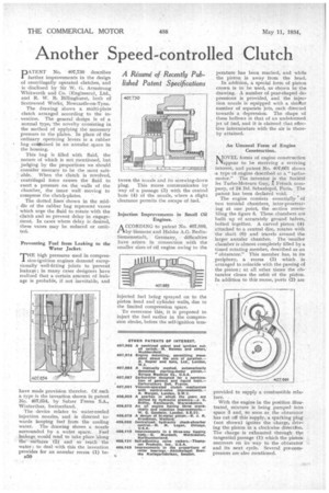
A Resume. of Recently Published Patent Specifications PATENT No. 407,730 describes further improvements in the design of centrifugally operated clutches, and is disclosed by Sir W. G. Armstrong Whitworth and Co. (Engineers), Ltd., and R. W. B. BiIlinghurst, both of Scotswood Works, Newcastle-on-Tyne.
The drawing shows a multi-plate clutch arranged according to the invention. The general design is of a normal type, the novelty consisting in the method of applying the necessary pressure to the plates. In place Of the ordinary operating levers is a rubber bag coat:tined in an annular space in the housing.
This bag is filled with fluid, the nature of which is not mentioned, but judging by the proportions we should consider mercury to be the most suitable. When the clutch is revolved, centrifugal force causes the fluid to exert a pressure on the walls of the chamber, the inner wall moving to compress the clutch-plates.
The dotted lines shown in the middle of the rubber bag represent vanes which urge the fluid to rotate with the clutch and so prevent delay in engagement. In cases where delay is desired, these vanes may be reduced or omitted.
Preventing Fuel from Leaking to the Water jacket.
THE high pressures used in compression-ignition engines demand exceptionally well-fitting joints to 'prevent leakage ; in many cases designers have realized that a certain amount of leakage is probable, if not inevitable, and
have made provision therefor. Of such a type is the invention shown in patent No. 407,654, by Sulzer Freres S.A., Winterthur, Switzerland.,
The device relates to water-cooled injection nozzles, and is directed towards keeping fuel from the cooling water. The drawing shows a nozzle surrounded by a water space. Fuel leakage would tend to take place 'along the surfaces (2) and so reach the water ; to deal with this the invention provides for an annular recess (1) be
B50 tween the nozzle and its screwing-down plug. This recess communicates by way of a passage (3) with the central bore (4) of the nozzle, where a slight clearance permits the escape of fuel.
Injection Improvements in Small Oil Engines.
A CCORDING to patent No. 407,889, 1-1by Siemens and Halske A.G. BerlinSiemensstadt, Germany, difficulties have arisen in connection with the smaller sizes of oil engine owing to the
injected fuel being sprayed on to the piston head and cylinder walls, due to the limited compression space.
To overcome this, it is proposed to inject the fuel earlier in the compression stroke, before the self-ignition tern perature has been reached, and while the piston is away from the head.
In addition, a special form of piston crown is to be used, as shown in the drawing. A number of pear-shaped depressions is provided, and the injection nozzle is equipped with a simPar number of separate jets, each directed towards a depression. The shape of these hollows is that of an undeformed jet of fuel, and it is claimed that effective intermixture with the air is thereby attained.
An Unusual Form of Engine Construction.
MOVEL forms of engine construction Nappear to be receiving a reviving interest, and patent No. 407,661 shows .a type of engine described as a " turbomotor." The inventor is the Socieni les Turbo-Moteurs Guy, t, French company, of 24 Bd. Sebastopol, Paris. The patent has been declared void. : The engine consists essentially of two toroidal chambers, inter-penetrating at one point, the section resembling the figure 8. These chambers are built up of accurately ground halves, bolted together. A curved piston (4) attached to a central disc, rotates with
• the shaft (6) and travels around the larger annular chamber. The smaller chamber is almost completely filled by a timed rotating member, described as an "obturator." This member has, in its periphery, a recess (3) which is arranged to coincide with the passing of the piston ; at all other times the ohturator closes the orbit of the piston. In addition to this recess, ports (2) are
provided to supply a combustible mixture.
With the engine in the position illustrated, mixture is being pumped into space 3 and, so soon as the obturator has cut off this supply, a sparking plug (not shown) ignites the charge, driving the piston in a clockwise directkm. The charge is exhausted through the tangential passage (1) which the piston uncovers on its way to the obturator and its next cycle. Several pre-compressors are also mentioned.