


Regent Omnibuses and Wagons.
Page 8
If you've noticed an error in this article please click here to report it so we can fix it.
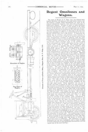
The name of Messrs. S. F. Edge, Ltd., has hitherto been largely identified with pleasure cars and marine motors, but the business acumen which characterises the head of the concern induced the company, more than four years ago, to build heavy vehicles. Pressure of orders in other directions prevented development until a recent period of the latter portion of the business, but such arrangements are in hand as to ensure deliveries to customers in the early part of June. The line drawing that appears on this page is the first that has been published in which any technical details of the new
Regent vehicles have been made known. It represents the chassis for an omnibus, and possesses many features of interest. The framework is built up of channel steel, having cross strengthening members at intervals, with the front portion cambered in just to front of the dashboard, permitting a large turning movement of the steering wheels. The four-cylinder engine develops eeh.p. at the normal speed of Soo revolutions per minute, each piston having a bore of momm. and a stroke of teemm. The exhaust and inlet valves are placed at opposite sides of the cylinders, these latter being cast in pairs. For cooling purposes a large honeycomb radiator is formed as a finish to the bonnet, having behind it a belt-driven fan, the water circulation being maintained by a gear-driven centrifugal pump. This pump is fitted on the exhaust side of the engine. Magneto ignition is employed, the armature being driven by the inlet valve cam shaft and advance effected by a lever working upon a sector upon the steering column, but quite separate from the steering wheel itself. .1 separate sector is used for the throttle lever. The transmission is by a large diameter leather-lined cone clutch (forming an integral portion of the flywheel) to a propeller shaft with encased universal joints at each end, which in its turn gives motion to the primary shaft in the oil-retaining and dust-excluding gear-box. The gear change is upon the locking-gate system, by one lever for the four forward speeds and reverse, whereby it is impossible to run through or miss gear when changing. The reverse can only be brought into action by lifting a catch, and when released from any gear the change speed lever automatically remains in the neutral position. From the secondary shaft in the gear-box the engine motion is conveyed by a bevel wheel to the differential, which is fitted upon a shaft at right angles to the line of the frame. The ends of this shaft are extended outside the frame, being carried by bearing brackets attached thereto, and have at their extreme ends driving sprockets for the two side roller chains, These sprockets are run up on threads and held in position by lock nuts and washers, so that renewals or alterations of gear can be easily arranged. The usual provision is made for chain adjustments by means of chain struts attached, as to the front ends, to the bearing brackets of the differential shaft, and as to the back ends, to the solid rear axle. Five brakes are fitted. The left-hand pedal on the driver's footboard releases the clutch, the righthand pedal also releases the clutch, and when it is quite free applies three external band brakes. One of these brakes is attached to the propeller shaft immediately in front of the gear-box (shown in the illustration just in the centre of the frame), the other two being carried by the differeniial shaft. The driven sprockets bolted to the rear wheels form drums for the two internal expansion brakes, which are actuated by a side lever conveniently placed for guide access by the driver. We attach particular importance to the number of brakes fitted, as the strain is the more equally distributed over the mechanism, and there is less risk of accident if one should fail at a critical moment. The petrol supply tank is immediately at the rear and is pressurefed to an auxiliary tank on the dashboard, whence it reaches the carburetter by gravity only. The exasperating hand air pressure pump to petrol tank is therefore abolished, arid it is always possible to start immediately from; the cold without necessity of wasting time and energy in forcing the petrol from tank to carburetter. The importance of ample lubrication has not been overlooked, and a range of.sightfeed drip lubricators on the dashboard communicate with the engine and all the main bearings.