


Abridgments of Interesting Patent Specifications.
Page 24
If you've noticed an error in this article please click here to report it so we can fix it.
Du Cros Ignition : Thier Cylinder Liner : Cannstatt Safety Starter.
No. 12,741 : Dated June 6, rgoa.-Harvey du Cros, of 14, Regent Street, Lanion.-An electric ignition device fcr internal combustion motors, which allows of utilising either a magneto or a battery or accumulator as des.red. The system of ignition employed is the wall-known system of magneto ignition, in which the current is directed into the circuit of a shunt coil from the primary circuit, closed off front the armature of the magneto by the interruption of this latter circuit. The variations of intensity in the shunt circuit ensure the production of the induction current in the secondary circuit. This system has been slightly modified in order to allow of introducing into the primary circuit another source of electrical supply, viz., a battery or accumulator, and of causing the ignition to operate either by this second source of electricity, or by the magneto, whilst retaining the coil without trembler, the rupture device of the magneto producing the interruptions of the battery or accumulator current so as to give rise to the secondary current. The magneto x carries three terminals-a, 3, and 4, one of which, viz., the terminal 2, is connected by means of a wire with the contact stud 5 of a special commutator 6, the purpose of which is to allow, by merely shifting a conducting blade 7 around an axle 8 of employing the magneto or the battery as desired, or likewise of preventing any current from passing into the coil This commutator carries three contact studs 5, g, and to insulated from the metallic mass of the conimutator and a fourth stud it electrically connected with the aforesaid axle 8. The electric connections are effected in the following way :-The terminal 12 of the winding 14 of the shunt coil from the primary circuit is connected with the terminal 3 of the magneto and the terminal 13 with contact stud in of the commutator. Terminal 4 of the magneto is connected on the one hand with contact stud Ii of the commutator, and on the other hand with the condenser 15, connected in its turn with terminal 3 of the. magneto. Finally, between the terminals 3 and 4 is fixed the current breaker 16, and the terminals of the battery 57 are connected with the contaet studs 9 and to of the commutator. When it is desired to utilise the magneto current, the conducting blade of the comniutator is placed in the position 10.8.5. The current produced by the magneto may then take two courses. If the platinised contacts of the current breaker 16 are separated from each other, the current will take the path 2, 5, 8, io, 13, 14, 12, 3. If the platinised contacts are in touch, the current will fellow the circuit of lesser resistance 2, 5, 8, tr, 4, 16, 3, and will not traverse the coil 14. The variations in the intensity of the current in the coil 14 will produce induction currents in the secondary curcuit x8. If it is desired to use the current of the battery in the position 8, 9, the current will follow the circuit 57, 9, 8, ii, 4, t6, 3, 12, 14, 13, 10, 17, and will be unable to take any other course. Whenever the platinised contacts of the current breaker 16 are separated, the current will be interrupted, and these interruptions of the primary current will give rise to the secondary current, Finally, if it is desired to interrupt the current in the coil, the conducting blade is placed in the position 8, 1, and the primary winding 14 of the coil no longer receives any current, either from the magneto or from the battery. This system allows of having a second source of electricity available in the case of the magneto failing to operate, by using the same coil as that employed with the magneto, but the current from the generating battery or accumulators being unable at any time to traverse the magneto armature, and the magnetic current unable to traverse the battery. It likewise allows oi easily producing ignition at the time of starting the motor. At that moment, particularly with powerful motors, the motor moved by hand turns very slowly, and the electro-motive force produced by the magneto may be insufficient to give rise to the secondary current and the spark. The battery is then used. The electromotive power of the battery being constant, the break of the current gives rise to a secondary current sufficient to produce the spark.
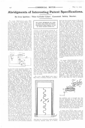
No. 7,740: Dated March 3xst, x904.Max Thier, of Erfurt, Prussia.-A renew built into the circular section of the cylinder and provided on their longitudinal sides with teeth and intervals (c, ele by means of which they are connected one with the other in such a manner that as a whole they constitute a tube, which covers the inner face of the cylinder as far as the path of the piston is concerned. In order to prevent, as wear takes place, chattering of the separate parts of the liner, a tension ring, an endless spiral spring (x) may be arranged between the liner and the cylinder wall (a). To prevent dirt from lodging behind the strips of which the liner is composed and thereby destroying their capacity for the necessary free movement, and in addition the contact of the liner with the cylinder body and consequently the desired cooling effect from the water-cooled cylinder wall, the cylinder bore is tapered towards the interior, and the separate strips of the liner are conespondin,gly farmed wedge-shaped. Provision is thus made that when wear of the sliding surface has taken place, the tube forming the liner can be forced forward by a suitable cap (d), so that a continuous contact between the cooling cylinder wall and the liner is ensured and the lodgment of foreign bodies between the two is prevented.
No. 23,990: Dated November e, 1904.C. A. Von Soden-Fraunhofen and the Daimler Motoren Gesellschaft, of Cannstatt, Germany.-The clutch portion A of the starting handle is connected by suitable mechanism with the cam shaft B operating the exhaust or induction, valves, and this shaft is free to slide longitudinally so that, when the clutch portion A is advanced to engage the opposed clutch part C for the purpose of starting the engine, the shaft B will be moved longi
tudinally. The operating cam on the shaft is provided with an additional cam B1, so that when the shaft is advanced
this auxiliary cam is brought into line with the operating rod of the valve and prevents complete closure of the valve during compression, for the purpose of relieving the effort required to start the engine. As soon as the engine starts, the operating handle with its clutch part A is again withdrawn, and the normal operation of the valve or valves restored.
A steam lorry driver, with a load of beer in barrels, was taking water last week outside a public house in London. The suction hose was run down into the cellar to lift from a pail replenished from the main. Said a loafer to his mate : "I'm blowed if they hain't pumping the blooming beer clown the cellar. Won't want any barrels soon !"