


Hydraulic Operation for Inj ectors
Page 26
If you've noticed an error in this article please click here to report it so we can fix it.
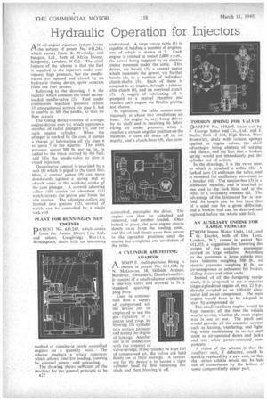
AN oil-engine injection system forms the subject of patent No. 611,243, which comes from R. Worledge and Integral, Lid, both of Africa House, Kingsway, London, W C.2. The chief feature of the scheme is that the fuel is supplied to the injectors under continuous high pressure, but the needlevalves are opened and closed by an hydraulic timing device, quite separate from the fuel system.
Referring to the drawing, I is the injector which contains the usual springloaded needle-valve (2). Fuel under continuous injection pressure (about 35 atmospheres) arrives via pipe 3, but is unable to lift the needle, so that no flow occurs.
The timing device consists of a single engine-driven cam (4) which operates a number of radial plungers (5), one for each engine cylinder. When the plunger is worked by the cam, it pumps a charge of lubricating oil via pipe 6 to space 7 in the injector. This extra pressure, about 300 lb. per sq. in., is added to the force exerted by the fuel, and lifts the needk-Yalve to give a timed injection.
Quantitative control isprovided by a unit (8) which is piped to the timer line. Here, a control piston (9) can move downwards against a spring and so absorb some of the working stroke of the cam plunger. A screwed adjusting collar (10) carries an abutment (11) which 'arrests the piston and limits the idle motion. The adjusting collars arc formed into pinions (12), several of which can be controlled by a single rack-rod.
PLANT FOR RUNNING-IN NEW ENGINES
DATENT NO. 611,247, which conies from the. Austin Motor Co., Ltd., and others, Longbridge Work s, 13irminghani, deals with an interesting
method of running-in newly assembled engines on a quantity basis. The scheme employs a rotary conveyor which .allowS time for loading, running by external power, and unloading.
The drawing shows sufficient of the machine for thegeneral principle' to be understood. A large rotary table (1) is capable of holding a number of engines. one of which is shown at 2. Each engine is rotated at about 2,000 r.p.m., the power being supplied by an electric motor mounted under" the table. This drives, via bevels (3), a central sleeve which transmits the power, via further bevels (4), to a number of individual clutch-shafts (5). Each of these is coupled to an engine, through a releaseable clutch (6), and an overload clutch (7). A supply of lubricating oil is pumped to a central chamber and reaches each engine via flexible piping, not shown.
In operation, the table rotates continuously at about two revolutions an hour. An engine is, say, being driven by its shaft and is receiving its lubricating oil under pressure; when it reaches a certain angular position on the machine, a cam (8) shuts off its oil supply, and a clutch-lever (9), also cam controlled, uncouples the drive. The engine can then be unbolted and removed, and another loaded. Once bolted in place, the new engine moves slowly away from the loading point. and the oil and clutch cams then return to the operative positions until the engine has completed one revolution of the table.
A CYLINDER AIR-TESTING ADAPTOR ASIMPLE multi-purpose fitting is shown inpatent No. 611,128; by N. McGowan, 38, Hillside Avenue, I3urnbrae, Alexandria, Dumbartonshire. It consists of a small adaptor containing a one-way valve and screwed to fit a standard sparking
plug bore.
Used in conjunction with a supply of compressed air, the device can be employed to test the gas-tightness of a piston and rings by blowing the cylinder to a certain pressure
-and noting the degree of leakage. Another
• use is in connection with the removal of valve-springs; if the cylinder be kept full • of compressed air, the valves are held , firmly, on to their seatings. A further use for the device is to loosen a tight • cylinder head by first loosening the studs and then blowing it off. TORSION SPRING FOR VALVES
PATENT No. 610,669, taken out by George Salter and Co.' Ltd., and J. Bache, both of 144, High Street, West Bromwich, deals with torsion springs applied to engine valves, the chief advantages being absence of surging and silence, and the fact that a broken spring would not immediately put the cylinder out of action.
In the drawings, 1 is the valve stern to which is attached a collar (2). A forked arm (3) embraces the valve, and is mounted for oscillatory movement in a bracket (4). The torsion-bar (5) is a laminated member, and is attached at one end to the fork boss and at the other to a stationary member (6). The advantage of the laminated bar is twofold; its length can be less than that of a 'solid one for a given deflection, and a broken leaf can be detected and replaced, before the whole unit faits.
AN AUXILIARY ENGINE FOR ,LARGE VEHICLES
FROM Simms Motor Units, Ltd., and G. Liardet, both of Oak Lane,, London, N.2, comes in patent No. .611;253, a suggestion for lowering the . weight of the auxiliary equipment carried on large vehicles. According to the patentees, a large vehicle may have batteries weighing 500 lb., an electric generator weighing 85 lb., an • air-Compressor or exhauster for brakes, sliding doors and other units.
Instead of all the foregoing equipment, it is proposed to use a separate single-Cylindered engine of, say, 2i h.p., directly coupled to an 110-volt alternator and an air compressor. The main engine would have to be adapted to start by compressed air
The small auxiliary engine would be kept runnin; all the time the vehicle was in service, whether the main engine was in use or not. The small unit would provide all the essential services such as heating, ventilating, and lighting, while maintaining in service such units as air-operated doors and jacks, and any other power-operated components.
A virtue' of the scheme is that the auxiliary unit, if defective, could be quickly replaced by a new one, so that the entire vehicle would not be held out of commission by the failure of some comparatively minor part.