


IMPROVEMENTS IN TRACTOR TRAILER DESIGN.
Page 32
If you've noticed an error in this article please click here to report it so we can fix it.
A Resume of Recently Published Patents.
AMONGST this week's patent specifi-cations' there are two which covet improvements•in the construction of sixwheeled tractor-trailer combinations. The first of them stands to the credit of
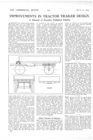
Hoare, already well known in the commercial motor industry for his successful inventions, amongst which that of the chain driven Tasker tractor is an outstanding, example. in the present invention, which is described in specification No. 210,225, ha has devised a novel method of attaching the trailer to the tractor, and of mounting the trailer upon its axle.
The connection between the tractor and trailer is a hemispherical universal joint. A hellow hemisphere is bolted, by means of a substantial Flange, to the frame of the tractor. It is embraced by two hol
low pieces of the same form. One of them, the outer, is secured by a flange to the main front cross-member of the 'iudy -of the trailer, and is, in the example illustrated in the drawing which accompanies the specification, partly embedded in that cross-member. The other, the inner one, is made integral with the king pin, which passes through a clearance hole, and is large enough to permit the necessary freedom of movement to the univessal joint.
The arrangement, it will be gathered,. i5 such as to relieve the king pin of all driving strain, this being entirely supported by the extensive and substantial hemispherical parts, which, by their shape and disposition, permit of freedom of relative movement between tractor and trailer not only laterally, but also vertically, to allow of that peculiar motion which is necessary when negotiating hump-backed bridges or narrow dips in the road.
The rear end of the trailer is mounted on the turntable of a bogie. The connection between the upper portion of that turntable and the trailer is, however, a sliding one, and the bogie itself
B48
is coupled to the tractor by special means. A horizontal triangular frame is rigidly attached to the bogie, and extends forward carrying one-half of a joint of the ball type. A similar triangular structure extends rearwarclly from the tractor frame, to which it is attached by a-horizontal hinge. The ball joint which connects these two triangular frames is located midway between the rear axle of the tractor and that of the trailer. The ball joint, acting in conjunction with the hinge by which the forward triangle is secured to the tractor, affords the necessary freedom of movement, and the arrangement of the joint, half way from axle to axle, ensures that the rearmost wheels :shall track truly with the others, IN the other invention which has as its object the improvement of the consruetion of this type of vehicle, a conical king pin is used, and the novelty
consists in the supplementary coupling means between tractor and trailer. These take the form of long parallel guide bars, sliding in bearings on the frame of the trailer, and carrying coiled springs, two to each bar, one in front of, and one behind, each bearing. The guide bars are coupled, by universally jointed links, to the rear of the tractor, and it is claimed that the springs counteract and prevent the tendency of the trailer to sway out of the track, to cut corners, or to bump up and down excessively. The patentee is A. Smith, and the specification is numbered 210,129.
Other Patents of Interest
AN improved arrangement of the in duction piping of a four-cylinder fourstroke engine is described in specification No. 210,123, by H. Ricardo. There are two induction; manifolds, each 'of which serves two cylinders only, the arrangement being such that each pipe serves those two cylinders the inlet
valires Of which are so actuated that there are equal time intervals between their successive openings.
A single carburetter supplies the two, and is connected to them by a Y pipe, in which the angle ia fairly acnte. With such an arrangement, if cylinder No. 1 performs its induction stroke and the closing of its inlet valve sets up oscillations in the horizontal induction conduit connecting it with cylinder No. 4, these oscillations do not have any appreciable effect on the combustible mixture in the vertical conduit communicating with the carburetter, and still less so as regards the in the other manifold. . Further, owing to the time which elapses between the induction periods of each of the two cylinders which are connected by the one manifold, the said oscillations are practically stilled in the meantime, and their effect is negligible in regard to the induction operations of any one cylinder of the four. Finally, as no two cylinders draw consecutively from the same pipe, each cylinder receives a charge unaffected by the dos. ing of the inlet port of the preceding cylinder.'
-CARBURETTER construction is dealt with in patent . specification No. 191,400 by the Soc. Aeon. Solex, in which an interesting improvement is de scribed. There are two jets, apart from one for atarting. Each jet is independent. of the other, both as regards air sup• plies and choke tube as wall as communication with the induction manifold.
Both of them, however, are subject to the
same throttle valve, which is of the barrel type. There are supplementary wing valves, one to each jet, or carburetter element, as the inventor describes a unit consisting of jet, choke tube, wing valve, etc. The wing valves are interconnected with one another and with the main throttle valve, 20 that the main carburetter wing valve can only be opened when that of the slow-running carburetter (not the starting device, which is independent) is fully open and the barrel valve sufficiently open to give the slow-running device full scope.
THE device. described in specification No. 192,407, by Soc. des Etch. Malicet et Blin, provides for differential action of the front-wbeel brakes of a vehicle when it is rounding a corner, so that the restraining effect On the inside wheel is more than that on the outside one. The steerinopivot is set off the centre of the brake lever fulcrum, and a rack arid pinion gear, mounted on that fulcrum, is operated by the steering movement, to cause the differential action aforementioned.
THE steering gear which is described in specification No, 196,915, by Benz et Cie, is applicable only to chassis in -which the front axle is articulated at the centre so that each half may move, under the influence of the springs, independently of the other. The steering gear is mounted so that the lower end of the pendulum arm is in line with the centre about which the axle is articulated, thus eliminating any interference.