


Patents Completed.
Page 22
If you've noticed an error in this article please click here to report it so we can fix it.
Complete specifications of the following patents will be sent to any address in the United Kingdom upon receipt of eightpence per copy at Sales Branch, Patent Office, Holborn, W.C.
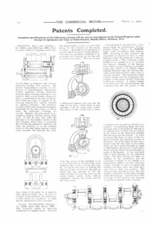
MAGNF.T0.—Bevis and Another.— No. 10,918, dated 20th May, 1908.—This invention relates to magnetos, and it has for its object to dispense with currentcollecting brushes and contacts. The present improvement consists in employing a high-frequency alternatingcurrent generator having stationary windings and a rotating inductor in conjunction with a transformer whose primary is connected to the said windings, and whose seecndary is capable of de. veloping high-tension current suitable for ignition purposes. The generator consists of the usual permanent magnets supported by the pole pieces, on which latter the stationary windings arc wound. Between the pole pieces is arranged a rotating inductor having three teeth. It will be seen that when the inductor is in the position shown in -the first diagram below there is maximum flux through the stationary windings, but when the inductor is in the position shown in the next figure there is a minimum magnetic flux through the wind
ings owing to the poles being magnetically short-circuited; thus, at each revolution of the inductor, six alternatingcurrent waves are produced. A hightension distributor is also provided.
VALVE M ECHANISM No. 6,659, dated 25th March, 1908.— This invention relates to operating mechanism for tappet valves. The pre
sent improvement consists in providing means for the variation of the timing of valves. Mounted on the camshaft is an arm which is free to rotate thereon. This arm has, pivotally connected to it, a curved arm carrying at its free end an anti-friction roller. This curved arm is interposed between the cam and the stem of the valve, which latter is also provided with an anti.friction roller. The radius of the curved arm is taken from the centre of the camshaft so as to avoid variation in the lift of the valve whatever the position of the arm may be. It will he seen that, by shifting the fulcrum of the curved arm, the time at vyhich the cam operates to lift the latter and thus to open the valve can be varied within certain limits without materially varying the actual amount the valve opens. CRANKSHAFT I3EARINGS.—Compagnie Beige de Construction D'Automobiles Usines "Pipe.------No. 16,894/08, dated under Convention 14th August, 1907.—According to this invention the crankshaft is mounted in ball or roller bearings within the crankcase in the following manner :—The crankcase is first heated in an oilbath so as to increase the internal diameter of the bearing holes, when an outer bushing or strengthening ring, which is of slightly larger external diameter than the internal diameter of the bearing holes when cold, is slid into position. The crankcase is then qiiicicly cooled, and the consequent contraction of the metal securely holds the bushing in position. A sleeve formed )f two halves is next placed between the inner-race ring and the journal of the teankshaft and secured by -thermal contraction. In assembling these, the inner ball-race ring is expanded by heating in an oilbath sc as to allow the two halves of the sleeve to be interposed hetween the race ring and the journal. In order to ensure the fixing of each of the two halves between the adjoining cranks of the shaft, one of the halves is first introduced from the free side of the crankshaft and then turaed through an angle of 180 degrees, the second is next introduced and the whole turned through an angle of 90 degrees. Iii this way each half is held laterally by the adjoining crank. The ball bearings are then assembled on the crankshaft, and the crankcase is heated in an ailbath to a temperature slightly less than that previously secured, in order to expand the bushing and thus allow the outer ballrace ring to slide into position. The whole is then allowed to cool ; the subsequent contraction of the metal securely holds the bearings. Application of this principle is also made to the hearings of gearboxes and for roller bearings.