


Improved "Hot-spot"
Page 34
If you've noticed an error in this article please click here to report it so we can fix it.
for an Induction System A Resume of Patent Specifications That Have Recently Been Published. Copies ma. y be Obtained from the Patent Office, Price 1 each
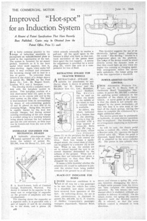
IT is fairly common practice in the *I design of induction manifolds to incorporate an exhaust-heated plate to assist in the vaporization of the fuel. The system is, however; by no means perfect, inasmuch as it is the least useful when most required, that is, when starting. Again, when under full load, it may overheat and attenuate the incoming charge and so lead to a loss of power. To overcome these defects is the object of a design shown in patent No. 552,208, by the Ford Motor Co., Ltd., 88, Regent Street, London, W.1, and J. Sampson.
The drawing shows a complete mani-. fold with the hot-plate system in section. This hot-plate consists of a thin sheet-metal bowl '(1). open to the exhaust on its convex side and to the inlet system on the other. The bowlis heat-insulated from its surroundings by means of non-conducting gaskets (2 and 3) placed on each Side. of its damping flange. Being thin, the bowl is rapidly heated by the first .few exhaust charges. but during normal running overheating of the new charge is avoided owing to a working balance being struck between the hot exhaust gas and the cold mixture, as little heat can be transfecred from the rest of the manifold.
HYDRAULIC EXPANDER FOR MECHANICAL BRAKES
AN hydraulic shoe-expander for, brakes operated by rods or cables forms the subject of patent No. 551,541, from the Rover Co., Ltd., and
P. A. Scott-Iversen, both of Chesford Grange, Kenilworth, Warwick. The device is claimed to be superior to the usual cam or wedge-type of expander on the grounds of simplicity and ease of-adjustment.
The drawing shows the expander as a separate unit ; it is provided with a pair of tappets (1 and 3) for abutting on to the shoes, and a piston (4) which extends externally to receive a pull-rod. All the spare space in the interior is filled with fluid, so that outward movement of the piston must force apart the two tappets. A means for adjustment is provided by a screw plug (2), which also acts as a compensator for loss of fluid.
RETRACTING STRAKE FOR TRACTOR WHEELS
jk RETRACTABLE STRAKE set,
suitable for attachment to any -tractor wheel, is shown in patent No. 552,203, by W. Bower and the Renishaw Iron Co., Ltd., Renishaw, near Sheffield.
552,205 This device
can be used on either the inside or the outside of the wheel,so that a variable track is available.
As.shOwn, the wheel, indicated by . a broken line. in the drawing, carries a ring (4) provided with a large number of bosses (2). Bolts
.PuJ1 die ring to the wheel, whilst
two distance pieces (1) on the periphery fix the position and at' the same tithe convey the drive. Each boss houses a spadeshaped strake, the round stem of which can be gripped by a setscrew (3) in the boss. When in use, the stmkes are set to extend beyond the tyre to an overall diameter determined by the softness of the ground. N'Vhen out of action they are retracted and given a quarter-turn, so that they then lie alongside the tyre wall.
It seems a little doubtful whether the setscrews (3) would be sufficient to prevent the .strakes from being pushed inwards if the ground be at all heavy.
, BLACK-OUT INDICATOR FOR BUSES
UNDER black-out conditions it is not at all easy for a bus passenger to be sure that the vehicle has come, to a standstill, and many accidents have occurred from ignorance of this fact. An indicating device, for use in these circumstances, is disclosed in patent No. 552,478, by G. F. Craven, of Halifax Corporation's passengertransport departmerit, Skircoat Road, Halifax.
This inventor suggests the use of an electrically lighted panel, displaying the words " Bus Moving," located in a conspicuous place on the platform. The lattips of the device would be wired directly across the dynamo leads so that they would light up only when the engine was running at charging speed. This arrangement makes the device quite automatic, the lamps going out as the bus approaches a standstill.
POWER-ASSISTED CLUTCH CONTROL
FROM Automotive Products Co., Ltd., and W. J. Brock, both of Tachbrook Road Leamington Spa, • comes, in patent No. 551,532, a scheme for applying power assistance to the operation of the dutch of a heavy vehicle. A novel point in the system is that the ditch . is not actually disengaged by the power. mechanism ; all that this does is to take most Of the load off the clutch springs, leaving the— driver to complete the withdrawal by a slight additional effort.
The motive power may be pneumatic or hydraulic, or even electric operation may be-employed. Our drawing 'shows an arrangement employing an hydraulic system.
As will be seen, the dutch pedal carries a control (6), which, throngh a Bowden cable (1), operates the liquid control valve (2). When the pedal is depressed, liquid from an accumulator (3) is admitted to the servo cylinder (4): The piston in this cylinder •then .
moves and stresses a spring (5), without, however, disengaging the clutch. A slight extra pressure from the driver can then complete the declutching operation. By this means, . the hard manual effort is abolished, without any sacrifice in delicacy of control. On the return stroke, the spring (5), remains operative until the Bowden control (6) is released, so that the same delicate control is obtained in both directions.