


Patents Completed.
Page 20
If you've noticed an error in this article please click here to report it so we can fix it.
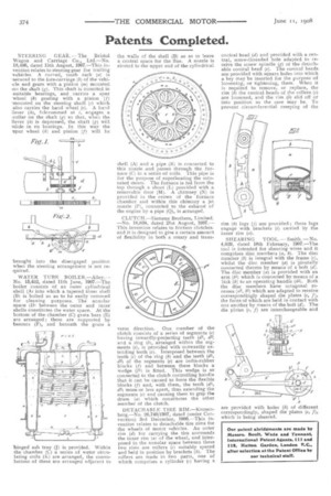
STEERING GEAR. — The Bristol Wagon and Carriage Co., Ltd.—No. 18,486, dated 13th August, 1907.—This invention relates to steering gear for trailing Lvehicles. A curved, tooth rack (a) is -secured to the fore-carriage (b) of the vehi and gears with a pinion (m) mounted -on the shaft (g). This shaft is mounted in suitable bearings, and carries a spur wheel (.6) gearing with a pinion (f) 'mounted on the steering shaft (c) which also carries the hand wheel (e). A hand ;lever (h), fulcrummed at engages a .collar on the shaft (g) so that, when the llever (h) is depressed, the shaft (g) will %tide iii its bearings. In this way the spur wheel (k) and pinion (f) will be
brought into the disengaged position when the steering arrangement is not re.quired.
WATER TUBE BOILER.—AlleyNo. 13,452, dated 11th June, 1907.—The boiler consists of an outer cylindrical shell (Ai into which a tapered inner shell (B) is bolted so as to be easily removed for cleaning purposes. The annular space (Di between the outer and inner shells constitutes the water space. At the bottom of the chamber (C) grate bars (E) are arranged ; these are supported by bearers (F), and beneath the grate a hinged ash tray (J) is provided. Within the chamber (C) a series of water circulating coils (K) are arranged, the convolotions of these are arranged adjacent to the walls of the shell (B) so as to leave a central space for the flue. A nozzle is riveted to the upper end of the cylindrical shell (A) and a pipe (R) is connected to this nozzle and passes through the furnace (C) in a series of coils. This pipe is for the purpose of superheating the saturated steam. The furnace is fed from the top through a shoot (L) provided with a removable door (M). A chimney (N) is provided in the crown of the furnace chamber and within this chimney a jet nozzle (P), connected to the exhaust of the engine by a pipe (Q), is arranged.
CLUTCH.—Siemens Brothers, Limited. —No. 18,834, dated 21st August, 1907— This invention relates to friction clutches. and it is designed to give a certain amount of flexibility in both a rotary and trans..
verse direction. One member of the clutch consists of a series of segments (e) having inwardly-projecting teeth (d1, d2) and a ring (b), arranged within the segments (e), is provided with outwardly extending teeth (c). Interposed between the teeth (c) of the ring (b) and the teeth (di, d2) of the segments (e) are india-rubber blocks (f) and between these blocks a wedge (f1) is fitted. This wedge is so connected to the clutch controlling handle that it can be caused to force the flexible blocks (f) and, with them, the teeth (d1, d2) more or less apart, thus extending the segments (e) and causing them to grip the drum (a) which constitutes the other member of the clutch.
DETACHABLE TIRE RIM.—Kronenberg.—No. 26,749(1907, dated (under Convention) 3rd December, 1906.—This invention relates to detachable tire rims for the wheels of motor vehicles. An outer rim (d) for carrying the tire surrounds the inner rim (al of the wheel, and interposed in the annular space between these two rims are rollers (c) suitably spaced and held in position by brackets (h). The rollers are made in two parts, one of which comprises a cylinder (c) having a conical head (d) and provided with a central, screw-threaded hole adapted to receive the screw spindle (g) of the detachable conical head (e). The conical heads are provided with square holes into which a key may be inserted for the purpose of loosening, or tightening, them. When it is required to remove, or replace, the rim (b) the conical heads of the rollers (c) are loosened, and the rim (b) slid off or into position as the case may be. To prevent circumferential creeping of the rim (I?) lugs (j) are provided ; these lugs engage with brackets (i) carried by the inner rim (a).
SHEARING TOOL. —Smith. —No. 4,029, dated 18th February, 1907.—The tool is intended for shearing wires and it comprises disc members (a, b). The disc member (b) is integral with the frame (c), whilst the disc member (a) is pivotally connected thereto by means of a bolt (d). The disc member (a) is provided with an arm (Al) which is connected by means of a link (k) to an operating handle (h1). Both the disc members have octagonal recesses (e22, A2) which are adapted to receive correspondingly shaped die plates (e, f), the faces of which are held in contact with one another by means of the bolt (d). The die plates (e, f) are interchangeable and are provided with holes (h) of different correspondingly, shaped die plates (e, f), which is being sheared.