


Rotary Fuel Pump
Page 64
If you've noticed an error in this article please click here to report it so we can fix it.
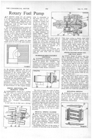
ANAN injection pump for oil engines is shown in patent No. 794,116. It is of the single-plunger type and has a rotary distributor for supplying several cylinders. (Simms Motor Units, Ltd., and Z. Miracki, both of Oak Lane, East Finchley, London, N.2.)
The actual pumping member consists of a pair of spring-separated plungers (1). These are diametrically _ located in the spindle and are carried round thereby. As they revolve, they are forced inwards by rollers (2) working inside a hollow cam ring (3). This creates the pumping stroke, the outward stroke being performed by the spring.
Fuel arrives from a gallery (4) when supply ports (5) are in the open position As the plungers approach, the fuel is forced through a delivery valve (6) and distributed to the various outlets by a revolving port (7) in the spindle. Regulation is provided by a sliding collar (8) on the spindle which controls spill-ports connected with the pumping space.
References are made to earlier patents numbered 733,270 and 743,688; which described a similar rotary pump. The present patent, however, covers a number of improvements on this original design.
SPRING MOUNTING 'FOR TRAILING AXLES
ASUSPENSION system for a trailing axle, either on a powered vehicle or a. trailer, is described in patent No. 794.241. The chief claims made for the Jesign are that its weight and moving masses are at a minimum. (DaimlerBenz A.G., Stuttgart Untertiirkheim, Germany.)
A rear axle (1), in this case a driving axle, is suspended in the usual way by leafsprings. Next to it, a, non-driven trailing axle is free to swing to a limited extent about a rubber-bushed attachment (2) mounted on a rotatable member (3).
The whole axle is free to slide sideways in metal bushed rubber sleeves (4); these are attached to a second set of leaf-springs (5). The outer ends of both sets of springs are shackled to the frame, but where they approach in the middle they are pivoted to rocking beams mounted on frame trunnions (6). This permits the springs to partake of a limited longitudinal movement.
When deflection has occurred, precompressed centring springs. (7) tend to urge the axle back into its normal position.
RUBBER-BUSHED FLEXIBLE COUPLING
AA FLEXIBLE coupling for accommodating limited axial misalignment is shown in patent No. 794,072. The universal movement is permitted by the resilience of a ball joint having a rubber intermediate member. (Metalastik Ltd., Evington Valley Road, Leicester.)
The joint is based on a pair of threeor-four-armed spiders (I and 2) having projecting pins (3) connected by links. The pins carry part-spherical bushes (4) which may alternatively be turned in one piece with the pin. The links are bored at each end and receive part-sphericai, sockets (5). These are split into three 120 degree segments and, in assembly, are placed over the rubber bush and forcefitted into place. The links will operate in either tension or compression, thus allowing the joint to be run in either direction.
HELICAL SPRING DAMPER
I-1 A HELICAL spring designed for heavy
duty work forms the subject of patent No. 794,875. The novelty lies in the incorporation of a damping device to prevent rebound and . oscillations during rapid deflection. (Metal Textile Corp., 647 East First Avenue, Roselle, New Jersey, U.S.A.) Surrounding the coils of the spring is a number of stave-like strips of metal (1). Their inner surface is thickly lined with resiliently compressible pads (2) made from a mass of compressed and compacted knitted or woven wire mesh. To hold the pads tightly against the coils, external garter springs (3) are placed around the outside. The damping action is given by the deforming of the pads when the spring lengthens and shortens.
PISTON HAYING RINGS ALL THE WAY DOWN
A NOVEL design of piston and ring
:A is disclosed in patent No. 794,889. [Cross Manufacturing Co. (1938), Ltd.. 33 Midford Road, Combe Down, Bath.] The form of the ring is that of a helical spring wound edge-on from flat ribbon.
The piston is shown in the drawing: it is screw-cut over its whole length at about seven grooves to the inch. The shape of the grooves is clearly shown, the most important point being that the lower face of each groove shall be less than the upper one.
The ring itself is a coil and is prefer ably divided into three sections, each having about five convolutions. When the rings are introduced into the cylinder bore, they are forced to tip slightly and so become tight in their groove. This gives a centralizing effect which prevents the piston moving sideways. It is possible to envisage circumstances in which the piston does not touch the cylinder at all.
ROTATING PISTONS
A SCHEME for making the pistons of
an engine rotate during running is shown in patent No. 794,282. No reasons are given for the requirement, which originates from Sulzer Freres S.A., Winterthur, Switzerland.