


PATENTS SUMMARIZED.
Page 22
If you've noticed an error in this article please click here to report it so we can fix it.
An Ingenious Differential-less Driving Axle. • • An ingenious contrivance which has for its object the elimination of the differential gear from a, driving axle has been patented by 8 J. Murphy. It is described in Specification No. 115,962. The inventor is particularly interested in the design of a four-wheel-drive agrimotor, and it is in connection with this machine that he has evolved thepdevice in question. • It is obviously, however, capable of broader application, and Buell application is covered by the 'patentee. The disadvantages of the ordinary typeof differential gear whici it in intended that this invention should overcome are that in the event of the resistance to traction failing on either wheel, that wheel continues to be driven, the one which has a grip of the road surface remaining stationary; and that lin the ordinary course the differential gear on the live axle necessitates a division of the axle at ornear its centre. Both of these failings are corrected in the ne.w gear, the principle of which is that of free-wheel-clutch, of which there is one in each wheel. The drive, however, in either the forward or reverse direction is a positive one.
On the driving shaft, and near each end, a screw thread is cut, on which, in each case, is mounted a nut. The nut is contained within a hollow portion of the wheel hub, with the interior of which it is held in frictional contact by means of fiat springs. The recess is but slightly larger in diameter than the nut, but is rattier wider. In each of the side walls are a number of projectingotuds, and these are adapted to engage with corresponding holes drilled in the nut. The arrangement is such, however, that the two sets of projecting studs may not be engaged • with the nut at one and the same time; in 'fact, the mid position of the nut is free from either set of .projections. It will readily be understood • that with the axle revolving in either direction the nut will, by reason of its frictional contact with the wheel hub, be caused to travel to the limit of possible movement laterally, thus being forced into engagement With the studs on the side to which it moves. A positive drive is thus transmitted from the axle to the wheer.
In order 1,6 release the wheel when the vehicle is rounding a corner, means are provided for temporarily binding the nut upon the axle. This takes the form of a radially disposed .pin extending from the inside of the hollow to a point underneath one of the threads of the nut,.
B48 This pin bears at its inner end upon a. flat piece of Spring steel, pivoted at its centre, and of such a length that its other extremity bears upon theinner end of a similar pin, and, normally, with the vehicle running in a straight path this pin projects through the outer cur
Lace of the axle and is covered by a recess in a sleeve on that axle. Means are then provided for moving the sleeve outwards towards that wheel which will be on the outer radius when the vehicle
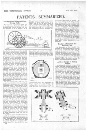
commences to turn, taus aepressing the latter named pin, and through the ineditnnof the flat steel bar pushing the first pin into close contact with the underside of the thread of the nut. As the wheel, owing to its being on the enter circumference, has simultaneously attempted to over-run the axle, and thus has pushed the nut out of engagement with the driving pegs, this in holds the nut disengaged until on straightening the steering the inner pin is again freed, and the nut takes up its customary driving position. One design of steering which performs this function is illustrated diagrammatieallY. It is shown applied to the fouri-wheel-drive tractor, but as it does not form the subject of the present invention, having previously had reference in these columns in our issue of the 30th May, further description is not necessary.
Tractor Attachment for Touring Cars.
R. Reynolds, in No. 114,551, has patented an attachment for any type of touring-car whereby the latter can be used as the motive poWer of a tractor, without disturbing its mechanism at all. The car is mounted upon a framework with its front wheels on. the ground, and its rear axle lifted on a jack, the tyres being brought into contact with large friction wheels, the latter driving the tractor wheels through spur gearing.
A New Design of Rotary Engine.
An attempt to eliminate reciprocating action from „the internal-combustion engine, is in the main the object of W. J. Scott, who patents a rotary engine in No. 114,469. A circular rotor carries piston-like valves, and in the interior of the rotor are suction and compression spaces. These piston-like valves induce the mixture into the interior of the rotor, remove it therefrom, and compress it again into another portion of the same interior. At the right moment the compressed mixture is admitted to a, passage east on the side of the rotor chamber, and ignited in the usual manner. The pressure due to the explosion acts On the side of one of the piston-like valves, causing rotary motion.