


Patents Completed.
Page 22
If you've noticed an error in this article please click here to report it so we can fix it.
A Multiple-Jet Carburetter.
D'Orsay McCall White and D. Napier and Son Ltd.—No. 12,244, dated 20th May, 1911.—According to this invention the csrburetter choke-tubes, inlet-tubes and throttle-connections are so arranged that, when starting the engine, the mixture is supplied at a high velocity from the carburetter, and at gradually decreasing velocity as the engine speeds up. In the construction illustrated, there are three jets, the central one of which has a choke-tube of smaller cross• section than the others. The choke-tubes communicate with the conduits leading to each of a pair of cylinders, and are controlled by a cylindrical throttle-valve. Preferably a gate-control is provided for the throttle, so that the carburetter shall not be inadvertently opened up completely by the sudden depression of the accelerator pedal.
A DiNerent Type of Carburetter.
Charles H. Pugh and G. F. Bull.—No. 14,805 of 1911, Cognate Application No. 20,227 of 1911, dated 26th June, 1911,— This carburetter is of the type in which a separate air current is used solely for atomizing the fuel, which is then mixed with the main air-supply to give the earrect mixture. A tapered tube in which the throttle-valve operates form the mixing chamber. One end of this tube is closed by a diaphragm from the centre of which a tapered air-jet extends {towards the right). The fuel-jet is introduced into this tapering tube at its narrowest point, so that the passage of air through the tapering tube draws the fuel out of the jet and atomizes it. In this state it passes into the middle of the mixing-chamber, and meets the main air-supply, which enters around the central tube. This air-supply is controlled by a hit-and-miss valve operated by a wire. The air supply for atomizing the fuel is drawn in by ports separate frorr those for the main air-supply.
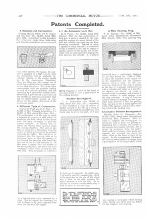
B.2/2 An Automatic Lock Nut.
B. S. Pierce.—No. 23,527, dated 24th October, 1911.—In this construction of lock nut, a pawl is carried by the nut, and this engages the screw thread of the bolt and entirely prevents the nut from becoming unscrewed. Instead of using a spindle to carry the pawl, a cylindrical recess is formed in the nut to engage a similar portion on the pawl; this is provided with an arm tapered to engage the bolt between the threads. A U-shaped
spring engaging a notch in the head of the pawl tends to turn it and hold it in the locking position.
Another Splashguard.
C. A. Richardson.--No. 30,345 of 1910, dated 31st ;July, 1911.--According to this invention a ring of rubber or leather is fixed to the side of a wheel to prevent mud splashing up sideways. The shield may be all in one part, or it may be built up of segments. In either case, it is held in place by a metal ring, which is the same size as the -rim of the wheel and is fixed on the side, gripping the shield between it and the rim. In an alternative construction the metal ring is held in place by screwed lugs.
A New Packing Ring.
E. II. Tartrais.—No. 18,855, of 1911, dated under International Convention 22nd August, 1910.—The packing ring
described here is particularly designed for use with Patent No. 17,565 of 1909, in which the cylinders of the engine act as the distributors for the explosive mixture which is used. In the construction illustrated, the ring is placed at the end of a passage communicating with a cylinder and slides on a distributor surface, not shown. A recess is formed round the passage, and a series of curved washers or other springs press the ring outwards. A ring of L-section is fitted inside the passage to form a gastight joint between it and the packing ring, one arm of the L lying against the walls of the passage, and the other entering a slot in the packing ring.
A Compact Daimler Arrangement.
Daimler Motor Co. (Germany).--No. 13,7813 of 1911, dated under International Covention 30th November, 1910.—In order to simplify the driving-gear for accessories and to make the general arrangement more compact, the spindle of the magneto is arranged vertically, and is driven by bevel-gear from the motorshaft, and the oil pump, water pump and magneto are arranged one above the other, either at the front or back of the engine. In the arrangement illustrated, the cooling water-pump is arranged upon a prolongation of the engine-shaft which also carries a bevel-gear wheel driving other wheels, one above and one below, for the magneto and oil-pump.