


A New Non-Slipping Device.
Page 6
If you've noticed an error in this article please click here to report it so we can fix it.
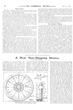
Inventors of non-slip devices for motorbuses have been very busy during the past year. The majority of their productions are, however, but feeble attempts to combat the growing evil of side-slipping, although a few of them possess some little merit. We recently examined one of the latter class, which, although involving a large num benof parts in its construction, may, if carefully designed and fitted to the driving wheels of a motorbus, prevent side-slip. We illustrate the device, which is the invention of Mr. E. B. Wayte, of 6, Osman Road, Shepherd's Bush, W., and Mr. F. C. Perkins, of
Greenside Road, Shepherd's Bush. Figure i shows a wheel fitted with the
device, which consists of twelve spring_ controlled, sliding bars (F) which slide in channel guides on the disc (C). All the parts are enclosed by the cover plate (D), which is provided with a hub, and is tree to revolve independently of the wheel-casting (A). The two plates (C and D) are securely bolted, at a definite distance apart, by means of distance bolts (E), and the sliding bars (one of which is shown apart in Figure 2) are normally retained in the channel guides on the disc (C) by plate springs (G), which bear up against the cover plate (0). The sliding bars have several buttress teeth cut in the side facing the cover plate (D) on which is fixed a single tooth (J) for each sliding bar. In normal running, the whole device rotates according to the requirements of the road surface and is not driven by the motor or in any way attached to the road wheels, other than bearing on the outer periphery of the wheel huh. The ring (I-I) acts as a cushion for the sliding bars, the inner ends of which are T-shaped, and their motion is thus restricted within certain limits by the inner ends of the channel guides on C. Assuming the slip of the wheel to be in the direction of the arrow (K), the sliding bar (F, Figure 3) is supposed to grip the road, and this action causes the teeth on the upper end of the sliding bar to engage With the single tooth (J). The sliding bar is LhL locked so long as it remains in contact with the road.