


Patents Completed.
Page 22
If you've noticed an error in this article please click here to report it so we can fix it.
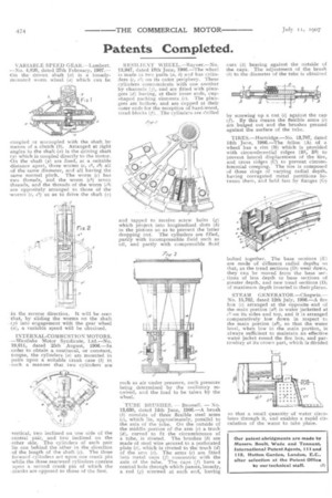
VARIABLE SPEED GEAR.—Lambert. —No. 4,826, dated 27th February, 1907.-On the driven shaft jx) is a looselymounted worm wheel (a) which can be • coupled or uncoupled with the shaft by means of a clutch (t). Arranged at right angles to the shaft (T') is the driving shaft (y) which is coupled directly to the motor.
the shaft (y) are fixed, at a suitable distance apart, three worms (c, el, c2) all -of the same diameter, and all having the same normal pitch. The worm (e) has -two threads, and the worm (el) seven -threads, and the threads of the worm (c2) are oppositely arranged to those of the --worms (e, ti) so as to drive the shaft (t-)
in the reverse direction, It will be seen that, by sliding the worms on the shaft
• (y) into engagement with the gear wheel (a), a variable speed will be obtained.
INTERNAL-COMBUSTION MOTORS. —Westlake Motor Syndicate, Ltd.—No, 19,011, dated 25th August, 1906.—In
• order to obtain a continual, or constant, torque, the cylinders (a) are mounted in pairs upon a suitable crank case (b) in
• such a manner that two cylinders are vertical, two inclined on one side of the central pair, and two inclined on the other side. The cylinders of each pair lie one behind the other irt the direction
• of the length of the shaft (e). The three forward cylinders act upon one crank pin while the three rearward cylinders operate upon a second crank pin of which the -cranks are opposed to those of the first. RESILIENT WlIEEL.—Rayner,—No. 13,947, dated 18th June, 1906.—The wheel is made in two parts (a, 1,) arid has cylinders jc, el) on its outer periphery. These cylinders communicate with one another by channels (j), and are fitted with plungers (d) having, at their inner ends, clipshaped packing elements (e). The plungers are hollow, and are cupped at their outer ends for, the reception of hard-wood, tread blocks (p. The cylinders are drilled and tapped to receive screw bolts {Al which project into longitudinal slots (h) in the pistons so as to prevent the latter dropping out. The cylinders are filled, partly with incompressible fluid such as oil, and partly with compressible fluid
such as air under pressure, such pressure being determined by the resiliency required, and the load to be taken by the wheel.
TUBE BRT_TSHES, — Bromell. — No. 13,630, dated 14th June, 1906.—A brush (b) consists of three flexible steel arms (e), which lie, approximately, parallel to the axis of the tube. On the outside of the middle portion of the arm (c) a truck (dj, curved to fit the circumference of a tube, is riveted. The brushes (b) are made of steel wire secured to a perforated plate (e), which is riveted to the truck (d) of the arm (c). The arms (c) are fitted into metal caps (j) concentric with the axis of the tube. The caps (f) have a central hole through which passes, loosely, a rod (g) screwed at each end, having nuts (h) bearing against the outside of the caps. The adjustment of the brush (b) to the diameter of the tube is obtained by screwing up a nut (i) against the cap Li). By this means the flexible arms (e) are bulged out and the brushes pressed against the surface of the tube.
TIRES.—Hartridge.—No. 13,707, dated 14th June, 1906.—The felloe (A) of a wheel has a rim (B) which is provided with circumferential ridges (B1, B2) to prevent lateral displacement of the tire, and cross ridges (C) to prevent circumferential creeping. The tire is composed of three rings of varying radial depth, having corrugated metal partitions between them, and held fast by flanges (C.)
bolted together. The base sections (E) are made of different radial depths so that, as the tread sections (I)) wear down, they can be moved from the base sections of less depth to base sections of greater depth, and new tread sections (I)) of maximum depth inserted in their places.
STEAM GENERATOR.—Chegwin.— No. 15,762, dated 12th July, 1906.—A fire box (e) arranged at the opposite end of the main portion WI is water jacketted at rf! on its sides and top, and it is arranged comparatively low down in respect to the main portion (a2), so that the water level, when low in the main portion, is always sufficient to maintain an effective water jacket round the fire box, and particulary at its crown part, which is divided
so that a small quantity of water circulates through it, and enables a rapid circulation of the water to take place.