


The Elements of Electrical Ignition.
Page 20
Page 21
If you've noticed an error in this article please click here to report it so we can fix it.
A Brief Explanation of Standard Systems,
In the case of multi-cylinder engines, the carrier (H) would have as many brushes (G) fixed thereon as there were cylinders to the engine. Each brush would be connected to a separate coil, and the switch would be situated at some other ,point in the circuit, say, between the terminal (A) and the battery. A single coil is now often used for multi-cylinder .engines, but it must be employed in conjunction with a hightension distributor, whose function is the distribution of the high-tension current of the one coil to each of the cylinders in succession, much the same as does the distributor which will be described later in connection with the high-tension magneto.
The Low-tension Magneto System.
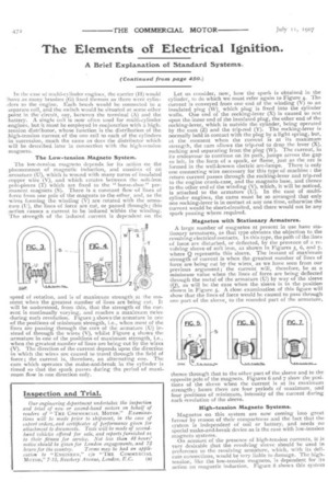
The low-tension magneto depends for its actinn on the phenomenon of magnetic induction, and consists of an :armature (U), which is wound with many turns of insulated .copper wire (V), and which rotates between the soft-iron pole-pieces (T) which are fixed to the " horse-shoe" permanent magnets (S). There is a constant flow of lines of force from one pole of the magnets to the other, and, as the wires forming the winding (V) are rotated with the armature (U), the lines of force are cut, or passed through ; this .action causes a current to be induced within the winding. The strength of the induced current is dependent on the -speed of rotation, and is of maximum strength at the mon-tent when the greatest number of lines are being cut, It will be understood, from this, that the strength of the curTent is continually varying, and reaches a maximum twice during each revolution. Figure 3 shows the armature in one of the positions of minimum strength, i.e., when most of the lines are passing through the core of the armature (U) instead of through the wires (V), whilst Figure 4 shows the .armature in one of the positions of maximum strength, i.e., when the greatest number of lines are being cut by the wires (V). The direction of the current depends upon the direction in which the wires are caused to travel through the field of force; the current is, therefore, an alternating one. The cam which operates the make-and-break in the cylinder is timed so that the spark passes during the period of maximum flow in one direction only. Let us consider, now, how the spark is obtained in the cylinder, to do which we must refer again to Figure 4. The current is conveyed from one end of the winding (V) to an insulated plug (W), which plug is fixed into the cylinder walls. One end of the rocking-lever (X) is caused to rest Upon the inner end of the insulated plug, the other end of the rocking-lever, which is outside the cylinder, being operated by the cam (Z) and the trip-rod (Y). The rocking-lever is normally held in contact with the plug by a light spring, but, at the moment when the current is at its maximum strength, the cam allows the trip-rod to drop the lever (X), rocking and separating from the plug (W). The current, in its endeavour to continue on its path, jumps across the gap so left, in the form of a spark, or flame, just as the arc is formed in the well-known electric arc-lamps. There is only one connecting wire necessary for this type of machine : the return current passes through the rocking-lever and trip-rod to the engine crank-case, and the magneto base, and thence to the other end of the winding (V), which, it will be noticed, is attached to the armature (U). In the case of multicylinder engines, the cams must be so arranged that only one rocking-lever is in contact at any one time, otherwise the current would be short-circuited, and there would not be any spark passing where required.
Magnetos with Stationary Armatures.
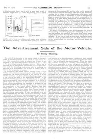
A large number of magnetos at present in use have stationary armatures, as that type obviates the objection to the revolving electrical contacts. In this type, the path of the lines of force are disturbed, or deflected, by the presence of a revolving sleeve of soft iron, as shown in Figures 5, 6, and 7, where Q represents this sleeve. The instant of maximum strength of current is when the greatest number of lines of force are being cut by the wires, as we have seen from our previous argument ; the current will, therefore, be at a minimum value when the lines of force are being deflected through the metal of the armature (U) by way of the sleeve (Q), as will be the case when the sleeve is in the position shown in Figure 5. A close examination of this figure will show that the lines of force would be caused to pass through one part of the sleeve, to the rounded part of the armature, thence through that to the other part of the sleeve and to the opposite pole of the magnets. Figures 6 and 7 show the positions of the sleeve when the current is at its maximum strength ; hence there are four periods of maximum, and four positions of minimum, intensity of the current during each revolution of the sleeve.
High-tension Magneto Systems.
Magnetos on this system are now coming into great favour by reason of their compactness and the fact that the system is independent of coil or battery, and needs no special make-and-break device as is the case with low-tension magneto systems.
On account of the presence of high-tension currents, it is very desirable that the revolving sleeve should be used in preference to the revolving armature, which, with its delicate connections, would be very liable to damage. The hightension, like the low-tension magneto, is dependent for its action on magnetic induction. Figure 8 shows this system in diagrammatic form, and it will be seen that a coil of insulated copper wire (V) forms the primary, around which another coil of very fine, silk-covered, copper wire (a) forms the secondary winding. One end of the primary is affixed to the core of the armature (U), and the other end is connecteil. to the contact-breaker bracket (b). One end of the secondary winding (a) is taken to the high-tension distributor, and from there the current is distributed to each of the sparking plugs in turn; the other end of this coil is connected to theprimary at a point which corresponds to the one which is marked 0 on Figure 1. The primary current, after passing through the primary coil (V), is conducted to the contactreaker (b, d, e, and f), where it is mechanically interrupted at the exact instant it is required. There is, at the moment of interruption, the same induction taking place as we have shown to be present in the ordinary coil ; therefore, a condenser is provided.
We would, in conclusion, warn drivers against the folly of disconnecting wires from plugs, then switching on the current, or running the magneto, and trying how long a spark can be obtained from the end of the wire to some point on the cylinder. If the gap is made so large that the sparks cease, there is a very great tendency for the high-tension current to find a path inside the windings, and to break down the insulation.