


A VIBRATION MODERATOR.
Page 66
If you've noticed an error in this article please click here to report it so we can fix it.
A Résumé of Recently Published Patent Specifications.
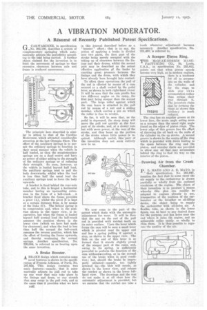
CARWARDINE, in specification Ur.No. 262,180, describes a system of complementary springing which automatically adjusts the periodicity according to the load being carried. A further object claimed for the invention is to limit the movement of springs 'so that excessive clearance between axle and frame is rendered unnecessary.
The principle here described is similar in action to that of the (Jardine Moderator, which attracted considerable attention at the last Olympia Show. The effect of the auxiliary springs is to permit the ordinary springs to function in their usual manner when the vehicle is half loaded, as then the supplementary springs are on a dead centre and have no power of either adding to the strength of the ordinary springs or of reducing their strength. So soon, however, as the vehicle is loaded beyond half load, the auxiliary springs tend to pull the body downwards, whilst when the load is less than half the usual load the auxiliary springs tend to force the body upwards.
A bracket is fixed behind the rear-axle tube, and to this is hinged a horizontal member having an upstanding extension in the form of a bell-crank. A bracket fixed above the frame provides a pivot (A), whilst the pivot B is kept at a certain distance from A by means of the links (C). The helical spring is in compression and, when iu the position shown in the upper view, is inoperative, but when the frame is loaded beyond half normal load the bell-crank assumes the position shown in the lower view (which we have had made for clearness), and when the load is less than half the normal the bell-crank assumes the reverse position, which has the effect of forcing the frame upwards, and thereby weakening the normal springs. Another specification, No. 220,084, is referred to as bearing upon the same invention.
A Brake Booster.
A. BRAKE design which contains some
novel features is shown in the specification of Francis Athimon, of Paris, No. 247,954. This design contains two main features—namely, that it automatically adjusts its pull rod to take up any wear that may take place in the linings and drum, or any stretch that may occur in the pull rods, and at the same time it provides what we have B46 in this journal described before as a " booster " effect ; that is to say, the action of applying a brake is divided into two parts, the first part of the stroke being merely occupied with the taking up of clearance between the linings and their drums, whilst the second part may be described as the actual effective application of the brake by exerting great pressure between the linings and the drum, with which they have already been brought into contact.
To effect these operations the pull of the rod is effected by means of a cam secured to a shaft rocked by the pedal lever, as shown in both right-hand view. It will be seen that the cam profile has two different angles on its ramp, the first part being steeper than the second part. The large roller against which the cam bears is attached to the pull rod by means of a nut and a sliding member, which carries a pin on which the roller is free to revolve.
So far, it will be seen that, as the pedal is depressed, the steep ramp will move the pull rod quickly at the first part of its stroke, and, at a slower rate but with more power, at the rear of the stroke, and thus boost up the portion of the stroke where little poweris required. Although useful, this part of the invention does not seem entirely new to us.
We now come to the part of the patent which deals with the automqtic adjustment for wear. It will be Seen that the nut on the end of the pull rod is provided with ratchet teeth on its outer surface. Upon the lever which forms the cam will be seen a small lever which is pivoted near its upper end and has a spring pulling it against a stop, as shOivn in the upper view. The blob on the end of this lever is so formed that it stands slightly proud of the steeper part of the cams, and, owing to its spring, is sufficiently powerful to perform the function of the • cam withoutscreceding, as in the normal use of the brake when in good condition; but, should the brake be improperly adjusted—namely, too tightly screwed up—the blob will recede, as shown in the lower view, and release the ratchet as shown in the lower lef thand view. The drawings and the text do not make it at all clear how the automatic adjustment is provided, but we surmise that the ratchet can take a THE McQUAY-NORRIS MANU FACTURING CO., St. Louis, U.S.A., in specification No. 255,812, points out that when piston speeds become very high, as in modern engines, there is a tendency for oil to accumulate on the walls of the cylinder, and for the rings to slide over tkis accumulation rather than scrape their way througli it. The inventors claim that by forming the rings as shown this 255.5'12 tendency is much reduced.
The ring has an angular groove at its lower face, the acute angle acting more as a scraper than the usual right angle found on the edges of piston rings. The lower edge of this groove has the effect of throwing the oil back on the walls of the cylinder on the up stroke. A second groove is shown in the centre of the ring which is provided with ducts leading to the space between the ring and the piston, and annular ducts are provided to allow any oil that may accumulate behind the ring to find its way to the interior of the piston.
-Drawing Air from the Crank Chamber.
p L. MAYO AND A. E. MAYO, in
their specification, No. 261,947, mention the fact that in some cases the air supply to the carburetter is drawn partially or wholly from the enclosed crankcase of the engine. The object of their invention is to produce a means whereby this plan can readily be adapted to engines already in use, irrespective of the position of the carburetter or the breather or oil-filling device, the object being to supply the carburetter with oil-laden air. A flexible tube, as shown in the lower figure, can be bent to any desired form for the purpose, and has holes near the end where it joins the engine, and an adjustable collar partly or wholly to close them. It is thus possible to regulate the quality of the air.