


A CHASSIS WITH DETACHABLE MAJOR UNITS.
Page 47
Page 48
If you've noticed an error in this article please click here to report it so we can fix it.
Another Method of Accelerating the Removal and Replacement of Components with a View to the Reduction of Maintenance Costs.
mHE reduction of maintenance costs is an aim which the
fleet manager ever has in view, and manufacturers of vehicles are willing, in prepari:.-s their designs, to help in any way which is reasonable and to adopt suggestions, provided they are likely to meet with general approval. A great deal has been done in this country to increase accessibility and rapid dismantling and replacement of component parts, and in our issue of November 23rd we deseribed a method which proceeded farther than anything previously iltrempted, in that the engine and gearbox, with radiator, exhaust box and petrol tank, were all carried on a subframe, which could be detached and withdrawn forwards in but a few minutes.
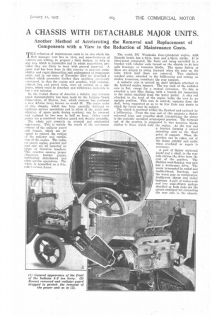
In the 'United States of America a definite step towards rapid demountability has been made by the Indiana Truck Corporation, of Marion, Ind., which concern has produced a new 4-5-ton lorry, known as model 41. The major units of this chassis, which has been specially designed to facilitate service operations and to allow of the quick substitution of spare parts during overhaul, can be removed and replaced by two men in half an hour. Other novel points are a combined radiator guard and shutter assembly.
The whole unit presents an unusual and substantial appearance. This is mainly the result of the uncommon contour of the radiator guard and bonnet, which are de
signed to control the cooling of the radiator and ventilation of the engine. The radia
tar guard, engine, gearbox and i-ear axle are all mounted on hinge or trunnion brackets.
This practice assures proper alignment, besides greatly facilitating detachment and other service operations. . The whole is assembled on a S-in. roltel-::ection frame.
The model DU Waukesha four-cylindered engine, with Ricardo heads, has a 4i-in. bore and a 61-in. stroke. It is three-point suspended, the front end being swivelled iii a bracket with tubular ends turned on the olitside to fit into split bearings, or trunnion blocks. The upper halves of these are hinged to swing forward when the nuts on the bolts which hold them are removed. Two similarly cranked arms, attached to the bellhousing and resting on similar trunnions, constitute the rear support. A radiator core is carried on shelf brackets attached to the forward engine support. The top tank of the radiator core is flat, except for a central extension. To this is attached a cast filler fitting, with a branch for connection to the outlet manifold from the water jacket. A stay rod attached to the head of the engine holds the core in an upright position. This core is entirely separate from the shell, being supported so as to be free from any strain to which the frame may be subject.
The clutch is mounted within the flywheel and enclosed by a bellhousing. From the rear end of this projects a Spicer universal joint and propeller shaft transmitting the power to the centrally mounted seven-speed gearbox. The forward end of the gearbox is supported in two trunnion blocks similar to those which hold the engine. At the rear end a bracket forming a swivel mounting acts as the third • point of support. Thus, the gearbox can be taken out of the frame quickly and easily when overhaul or repair is necessary.
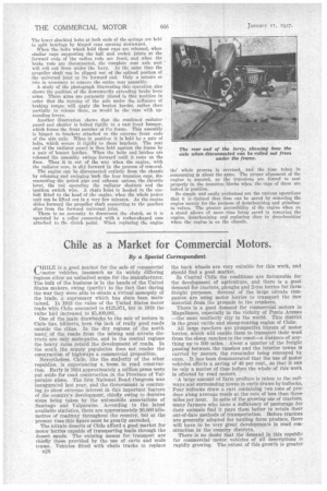
A pair of Spicer universal jointsr.and a shaft to the rear axle carries the drive from the rear of the gearbox. The Sheldon semi-floating rear axle has a worm-gear drive. The worm is mounted in radial and double-thrust bearings, and the worm gear on combination double-row thrust and radial bearings. A pair of radius rods and two semi-elliptic springs shackled at both ends are the means employed for connecting the rear axle to the chassis. The lower shackled bolts at both ends of the springs are held in split bearings by hinged caps opening downward.
When the bolts which hold these caps are released, when similar caps supporting the ball and socket joints at the forward ends of the radius rods are freed, and when the brake rods are disconnected, the complete rear axle unit will roll out from under the lorry. At the same time the propeller shaft can be slipped out of the splined portion of the universal joint at its forward end. Only a minute or two is necessary to remove the entire rear assembly.
A study of the photograph illustrating this operation also shows the position of the downwardly extending brake lever arms. These arms are purposely placed in this position in order that the turning of the axle under the influence of braking torque will apply the brakes harder, rather than partially to release them, as would be the case with upstanding levers.
Another illustration shows that the combined radiator guard and shutter is bolted rigidly to a cast front bumper, which forms the front member of ne frame. This assembly is hinged to brackets attached to the extreme front ends of the side rails. When in position it is held by a pair of belts, which secure it rigidly to these brackets. The rear end of the radiator guard is then held against the frame by n pair of bonnet latches. When the bolts and latches are released the assembly swings forward until it rests on the floor. Thus it is out of the way when the engine, with the radiator core, is slid forward in the process of removal. The engine can be disconnected entirely from the chassis by releasing and swinging back the four trunnion caps, disconnecting the petrol pipe and exhaust unions, the throttle lever, the rod operating the radiator shutters and the ignition switch wire. A chain hoist is hooked to the eyebolt fitted to the head of the engine, when the whole power unit can be lifted out in a very few minutes. As the engine slides forward the propeller shaft connecting to the gearbox slips from the forward universal joint.
There is no necessity to disconnect the clutch, as it is operated by a roller ponneeted with a rocker-shaped cam attached to the clutch pedal. When replacing the engine
the" whole process is reversed, and the time taken in remounting is about the same. The proper alignment of the engine is assured, as the trunnious are forced to seat properly in the trunnion blocks when the caps of these are bolted in position.
So simple and easily performed are the various operations that it is claimed that time can be saved by removing the engine merely for the purpose of decarbonizing and grindingin valves. The greater accessibility of the engine when on a stand allows of more time being saved in removing the engine, decarbonizing and replacing than in decarbonizing when the engine is on the chassis.