


An Automatic Electro magnetic Clutch
Page 26
If you've noticed an error in this article please click here to report it so we can fix it.
I NTEREST in the possibilities of
magnetic clutches seems to be re-awakening, and a new design for such a device is shown in patent No. 609,979: by J. laird, and .Joseph Lucas, Ltd., G reat King 'Street, Birmingham, 19.
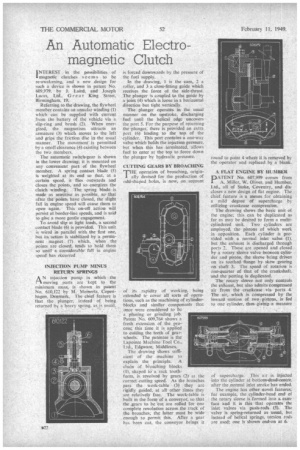
Referring to the drawing, the flywheel member contains an annular winding (1) which can be supplied with current from the battery of the vehicle via a slip-ring and brush (2). When energized, the magnetism attracts an armature (3) which moves to the left and grips the friction disc in the usual manner. The movement' is permitted by a small clearance (4) existing between the two members.
The automatic switch-gear is shown in the lower drawing; it is mounted on any convenient part of the flywheel member. A spring contact blade (5) is weighted at its end so that, at a certain speed, it flies outwards and closes the points, and so energizes the clutch winding_ The spring blade is made as sensitive as possible, so that after the p4rits have closed, the slight fall in engine speed will cause them to open again. This on-off action will persist at border-line speeds, and is said to give a more gentle engagement.
To avoid slip at light loads, a second contact blade (6) is provided. This unit is wired in parallel with the first one, but its action is stabilized by a permanent magnet (7) which, when the points are closed, tends to hold them so until a considerable fall in engine speed has occurred INJECTION PUMP MINUS RETURN SPRINGS
AN injection pump in which' the moving parts are -kept to the minimum mass, 14 shown in patent No. 610,122 by M. Meinertz, Copenhagen, Denmark. The chief feature is that the plunger, instead of being returned be a heavy spring. as is usual.
is forced downwards by the pressure of the fuel supply.
In the drawing, 1 is the cam, 2 a roller, and 3 a close-fitting guide which receives the force of the side-thrust. The plunger is coupled to the guide by a joint (4) which is loose in a horizontal direction but tight vertically.
The plunger operates in the usual manner on the upstroke, discharging fuel until the helical edge uncovers the port 5. For the purpose of returning the plunger, there is provided an extra port (6) leading to the top of the cylinder. This port contains a one-way valve which holds the injection pressure, but when this has terminated, allows fuel to enter at the top to force down the plunger by hydraulic pressure.
CUTTING GEARS BY BROACHING 'THE operation of broaching, origin' ally devised for the production of odd-shaped holes, is now, on account
of its rapidity of working, being extended tc cover all sorts of operations, such as the machining of cylinder-blocks and similar components that 'once were considered to be a planing or grinding job. Patent No 609,764 shows a fresh extension of the process; this time it is applied to cutting the teeth of gearwheels. The patentee is the Lapointe Machine Tool Co., Ltd., Edgware, Middlesex.
The drawing shows sufficient of the machine to explain the principle. A chain of broaching blocks I), shaped to a rack toothform, is revolved by gears (2) at the correct cutting speed. As the broaches pass the work-table (3) they arc rigidly guided, at allother times they are relatively free. The work-table is built in the form of a conveyor, so that the .gears to be 'cut are rolled for one complete revolution across the track of the broaches; the tatter must be wide enough to permit this. After a gear has been cut, the conveyor brines it
A FLAT ENGINE BY HUMBER DATENT No. 607,999 comes from A. Miller, W. Oliver, and Humber, Ltd., all of Stoke, Coventry, and discloses a new design of flat engine. The chief feature is a means for obtaining a mild degree of supercharge by utilizing crankcase compression.
The drawing shows the basic unit of the engine; this can be duplicated as tar as may be desired to form a multicylindcred unit. Two cylinders are employed, the pistonsof which work in opposition. Each cylinder is provided with a normal inlet valve (1), but the exhaust is discharged through ports 2. These are opened and closed by a rotary sleeve valve between cylinder and piston, the sleeve being driven on its toothed flange by skew gearing on shaft 3. The speed of rotation is one-quarter of that of the crankshaft. and the porting is duplicated.
The rotary sleeve not only controls the exhaust, but also admits compressed air from the crankcase via ports 4. The air, which is compressed by the inward motion of two . pistons, is fed . to one cylinder, thas .giving a measure of supercharge. This air is injected into the cylinder at bottom-dead-centre. after the normal inlet stroke has ended.
The engine has other novel features: for example, the cylinder-head end of the rotary sleeve is formed into a camface and it is this that operates the inlet valves via push-rods (5). The valve is spring-returned as usual, but instead of helical springs, torsion rods are used: one is shown end-on at 6.