


Patents Completed.
Page 22
If you've noticed an error in this article please click here to report it so we can fix it.
Complete sped! leaf ions of the following patents will be sent to any address in the United Kingdom upon receipt of eightpence per copy at Sales Branch, Patent Office, Holborn, W.C.
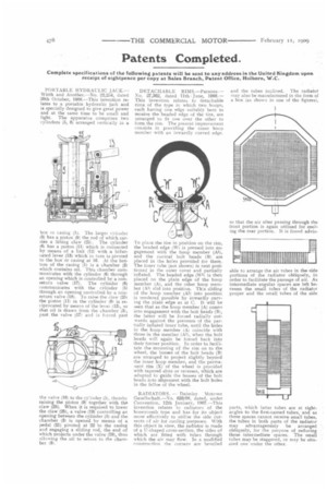
PORTAI3LE HYDRAULIC JACK.— Wirth and Another.—No. 22,254, dated 20th October, 1908.—This invention relaths to a portable hydraulic jack and is specially designed to give great power and at the same time to be small and light. The apparatus comprises two cylinders (5, 6) arranged vertically in a
box nt casing (1). The larger cylinder
(5) has a piston (9) the rod of which carries a lifting claw (251. The cylinder (6) has a piston (11) which is connected by means of a link (12) with a bifurcated lever (13) which in turn is pivoted to the box or casing at 16. At the bottom of the casing (1) is a chamber (3) which contains oil. This chamber communicates with the cylinder (6) through an opening which is controlled by a non. return valve (17). The cylinder (8) communicates with the cylinder (5) through an opening controlled by a nonreturn valve (18). To raise the claw (25) the piston (11) in the cylinder (6) is reciprocated by means of the lever (13), so that oil is drawn from the chamber (3), past the valve (17) and is forced past
the valve (18) to the cylinder (5), thereby raising the piston (9) together with the claw (25). When it is required to lower the claw (25), a valve (19) controlling an opening between the cylinder (5) and the chamber (31 is opened by means of a pedal (21) pivoted at 22 to the casing and engaging a sliding rod, the end of which projects under the valve (19), thus allowing the oil to return to the chamber (3). DETACHABLE RIMS—Parsons.No. 27,362, dated 11th. June, 1908.— This invention relates to detachable rims of the type in which two hoops, each having one edge suitably bent to receive the beaded edge of the tire, are arranged to fit one over the other to form the rim. The present improvement consists in providing the inner hoop member with an inwardly curved edge.
To place the tire in position on the rim, the beaded edge (WI is pressed into engagement with the hoop member (Al), and the conical bolt heads (B) are placed in the hoes provided for them. The inner tube (not shown) is next positioned in the outer cover and partially inflated. The beaded edge (W1) is then placed on the plain edge of the hoop member (A), and the other hoop member (Al) slid into position. This sliding of the hoop member (All into position is rendered possible by inwardly curving the plain edge as at C. It will be seen that as the hoop member (A) comes into engagement with the bolt heads (B), the latter will be forced radially outwards against the pressure of the partially inflated inner tube, until the holes in the hoop member (A) coincide with those in the member (Al), when the bolt heads will again be forced back into their former position. In order to facilitate the mounting of the rim on to the wheel, the bosses of the bolt heads (B) are arranged to project slightly beyond the inner hoop member, and the permanent rim (X) of the wheel is provided with tapered slots or recesses, which are adapted to guide the bosses of the bolt heads into alignment with the bolt holes in the felloe of the wheel.
RADIATORS. -Daimler Motoren Gesellschaft. —No. 633108, dated, under Convention, 12th January, 1907.--This invention relates to radiators of the honeycomb type and has for its object more effectively to utilise the side currents of air for cooling purposes. With this object in view, the radiator is made of a U-shaped cross-section, the sides of which are fitted with tubes through which the air may flow. In a modified construction the corners are bevelled
and the tubes inclined. The radiator may also be manufactured in the form of a box (as shown in one of the figures), so that the air after passing through the front portion is again utilised for cooling the rear portion. It is found advis
able to arrange the air tubes n the side portions of the radiator obliquely, in order to facilitate the passage of air. As intermediate angular spaces are left between the small tubes of the radiator proper and the small tubes of the side parts, which latter tubes are at tightangles to the first-named tubes, and as these spaces cannot receive small tubes, the tubes in both parts of the radiator may advantageously be arranged obliquely, for the purpose of reducing these intermediate spaces. The small tubes may be staggered, or may be situated one under the other.