


Compact Ram for Telescopic Bodies
Page 76
If you've noticed an error in this article please click here to report it so we can fix it.
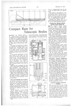
of the power piston. The pump crank carries a pinion (3) to transmit the drive to the auxiliaries. The extreme left end
PATENT No. 698,102 shows a vehicle having a telescopic body consisting of five separate sections, four of which can be closed into the fifth. The aim is to facilitate the discharge of light bulky loads. The patentees are Walkers and County Cars, Ltd., and E Tapp, both of Albert Street, Fleet, Hants.
The subject of the patent is a means for actuating the sliding sections by a hydraulic ram. Normally such a ram would require a space equal to twice its working stroke, but the patent explains a simple way of increasing the movement so that a short ram can be used.
In the general arrangement, 1 is the fixed section of the body; this can receive all the other four sections, one inside the next. The actuating ram (2) carries a pulley (3) which functions as one of the sheaves of a block-andtackle mechanism. The cable is attached to a fixed point at one end and a movable section of the body at the other.
When the ram is extended, the body section is thus made to travel twice the ram movement. The cables are duplicated in a fore-and-aft direction, so as to give a push-or-pull action, and more than one sheave may be used if a higher speed magnification is desired. Each of the body, sections is fitted with rollers for ease of movement, and the whole assembly is mounted on its own frame to avoid imposing stresses on the chassis.
NEW TWO-STROKE OIL ENGINE
ASMALL two-stroke oil engine for use in road vehicles and agricultural tractors is disclosed in patent No. 698,026 by Porsche Konstruktionen G.m.b.H., Schwieberdinger Strasse 141, Stuttgart-Zuffenhausen, Germany. The unit and its auxiliaries are laid out compactly.
In the drawing, 1 is the working cylinder which operates on conventional principles. The crankshaft is' extended leftwards by a screwed-on attachment which forms the crank of the scavenge pump (2). This pump is a large-bore short-stroke unit, having piston diameter of about I times that n42 carries a starting-handle dog (4) and a cam (5) which works the injection pump.
The machine is air-cooled by a fan (6) shaped so that the dynamo can be housed inside it (7). The fan and the dynamo are both driven by the same belt. An unusual feature is the provision of a power-driven oil filter (8).
Although the scheme refers to a single-cylindered unit, the patent covers the use of multi-cylindered engines.
HYDRAULIC BRAKE PISTON HOLDS LIGHT PRESSURE
MANY hydraulic braking systems work with a slight residual pressure, the object of which is to take up all slack in readiness for the actual braking. Patent No. 698,243 describes a means for creating and holding such a pressure, the operation being auto. matic. The patentee is S. A. Stabilimenta Farini, Turin, Italy.
The pressure-maintaining unit and the master cylinder are formed in one piece. The master piston is provided with an annular space (1) which is full of liquid. When the piston is pressed leftwards, this space acts as a pump and forces fluid through a one-way valve (2) into the vertical cylinder (3).
The cylinder houses a piston loaded by a spring which determines the value of the residual pressure. When the vertical cylinder is filled to capacity, any further liquid is able to escape through leaks (4) which are uncovered by the piston at the top of its stroke.
On the return stroke, the stored pressure reaches the main fluid system through a port (5) and small holes (6) which are uncovered by the master' piston at the end of the off-stroke.
INJECTION NOZZLE IMPROVED
ADETAIL improvement in the construction of injection nozzles is contained in Patent No. 698144 (C.A.V. Ltd., Warple Way, London, W.3). The object is to facilitate the seating of the needle valve despite minor inaccuracies.
When fuel arrives through port 1 it reaches annular channel 2 and lifts the valve to commence injection. So much is common practice, the difference in this case being that the actual closure member (3) is a separate piece which is not part of the main stem (4).
This means that the conical valve can accommodate itself to the seating without restraint from the stem. Otherwise they move as one. To ensure that no fuel can be trapped between the two members, a shallow recess (5), vented by the central bore, is used.
COOLING-WATER WARNING DEVICE
TO warn the driver if the cooling water falls below a safe level is the aim of a simple device shown in patent No. 696,654, by E. Snook, 39 Cowbridge Road, Bridgend, Glam. In the upper radiator hose is placed a pair of electrodes which will pass current when immersed in water, but not otherwise. Should the water level fall below this point, the current would cease and a suitable instrument on the dash would warn the driver of the fact.