


THE CROSSLEY SIX WITH FORWARD !:LER OL.
Page 16
Page 17
If you've noticed an error in this article please click here to report it so we can fix it.
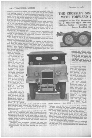
Designed to the War Departmel for a Medium-type Six-wh( I.G.L.3., Series 1, Crossley CI Large Loading Sp
ements e New ives a
THE specification to which this chassis has been built calls for 'a loading capacity of 4 tons on the road and 3 tons across country; consequently, a powerful engine is essential and, in this model, it is a four-cylindered pattern with a bore of 4A. ins, and a stroke of 5i ins., giving a capacity of 321.35 cubic ins., the b.h.p. developed at 1,000 r.p.m. being 47.5. The cylinders are cast in pairs and, of course, have detachable heads.
Lubrication is on the dry-sump principle, the oil being pressurefed to the five bearings of the crankshaft and the big-ends. The pump is carried in the sump and driven from the rear end of the camshaft. Circulation of the cooling water is effected by a centrifugal pump, it being passed through a vertical-type radiator of the header-and-bottom-tank type; cooling is assisted by a fan mounted on a ball-bearing hub. Carburation is effected by a Zenith vertical instrument, and ignition by -the Simms 8.11.4 h.t. magneto with a Simms vernier coupling. The camshaft is driven by a Renold silent chain, for which an adjustment is provided. The height of the oil in the separate chamber is ascertained in two ways—by an oil-level gauge mounted at the side of the engine and by high and low-level oil cocks.
It is rather unusual to find that the gearbox is not built as a unit with the engine and clutch, and on the clutch coupling are twin, fabric universal joints. The clutch itself is a single-plate pattern with Ferodo friction surfaces and a multiple-spring pressure plate. Ease of engagement is permitted by the provision of a spring-loaded clutch stop. The disengagement gear has a ball thrust and an adjustment is provided for the pedal position. Four forward speeds and a reverse are provided for normal use, but there is an auxiliary gearbox bolted to the rear of the main box, and this gives a further low-gear range for use in exceptional circumstances. The actual ratios are as follow, the normal range being given first : top, direct; third, 1.883 to 1; second, 3.291 to 1; first, 5.448 to 1; reverse, 4.4 to 1. For the auxiliary gear they are: top, 3.18 to 1; third, 6.0 to 1; second, 10.48 to 1; first, 17.34 to 1; reverse, 14.01 to 1. The ratio of the final drive is 7 to 1.
The shaft for the change-speed control is mounted in a tubular, cast extension on the gearbox, a connection being made between a lever on this shaft and the change-speed lever, which is, of course, mounted farther forward. All the gears are of nickelsteel, carefully heat treated, and the shafts, of course, run on ball bearings. An oil-level cock is provided to enable the correct level of the lubricant in the box to be ascertained.
Between the auxiliary gearbox and the bogie forward axle is a propeller shaft with all-metal universal joints, specially designed to permit large variations in the angle of drive and, at the same time, to form selfcontained oil reservoirs. A shorter propeller shaft with similar joints is utilized to join the driving worms of the bogie axles, both of which are carried above the worm wheels. One-piece steel stampings without tie rods are utilized for the axle casings. A large ball-thrust bearing is provided for the worm gearing and taper-roller .B32 bearings for the wheel hubs. The differential is of the bevel-pinion pattern and the axle is fully floating. An interesting point is that all parts of both axles a r e interchangeable, with the exception of the worm shafts.
We have already given the rear-axle ratio, and it may be of interest to include the total gear ratio between the engine and the road wheels. For the normal range these are: top, 8 to 1; third, 15.064 to 1; second, 26.528 to 1; first, 43.584 to 1; reverse, 36.2 to 1; and for the lower range: top, 25.44 to 1; third, 48.00 to 1; first, 135.72 to 1; reverse, 112.08
Torque rods of the now well-known W.D. pattern are fitted between the worm casings and a stout tubular cross member of the chassis, well-constructed ball joints being provided on the rods; these rods remove all torsional loading from the rear springs. Both sets of brakes are of the internal-expanding type and operate in drums bolted to all four rear wheels, four-wheel braking being effected both by hand and foot. The brakes have interchangeable shoes with Perodo facings and simple means for adjustment, that at the rear being by large wing-nuts.
A steel stamping of high-quality steel is employed for the front aide, which is of H-section between the road springs and of round section from the spring seats
to the swivel pins. The axle is what is known as the reversed —Elliott pattern -in other words, the jaws are on the stub axles instead of on the exle. The swivel pins have long plain bearings and ball-thrust races, whilst roller bearings are provided for the wheel hubs as in the case of the rear wheels.
With a vehicle of this description, steering is a matter of very great importance. The wheels may be subjected to all kinds of stress and, as when operating through sand and soggy ground, the power which has to be exerted upon the steering is consider able. However, it has been found satisfactory to incorporate a gear of the cam and roller pattern. The track rod is mounted at the back of the axle and the steering rod has spring-loaded joints. A point in the design is that the steering column is raised to give ample space for the accelerator pedal instead of the confined area often provided.
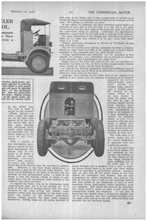
As regards the frame, this, in the illustration, looks comparatively light, but it is not actually so. It is made of alloy steel of channel section with five cross members of the some section and tubular crossmembers which form the mounting for the bogie axles, which are carried on two inverted semi-elliptic springs. Straps prevent the bogie axles dropping excessively: Towing loops are, of course, provided at both ends of the frame and a stout towing hook is carried on a strong laminated cross-spring mounted right across the frame at the rear. This fitting is, however, an extra.
In the vehicle we illustrate, the inter-connected petrol tanks are mounted at each side of the cab, that is to say, one to the right of the driver and the other close to the near-side door, the feed to the carburetter being by gravity. (Although the specification mentions a petrol tank on the dash with a capacity of 20 gallons.)
The main dimensions of the chassis are: wheelbase to centre of bogie, 12 ft.; bogie axle centres, 3 ft. 8i ins.; track with single tyres, 5 ft. 2 ins.
Chassis 'lubrication throughout is effected by Tecaletnit oil gun with swivelling nozzle.
The 12-volt starting and lighting equipment includes a dynamo driven by chain from the front of the engine and a starter spigot mounted on the crankcase with the usual Bendix drive.
Certain modifications and additions can be embodied in this chassis ; for instance, a h.t. distributor can be utilized in addition to the magneto, and a mechanical tyre pump fitted.
Single tyres at the front and twins at the rear are specified as standard, but 34-in. by 7-in., or 40-in. by 9-in. straight-sided Dunlop tyres, singles all round, can be fitted if desired. As regards the lighting equipment, acetylene headlamps and oil side and tail lamps can be fitted as an alternative, a corresponding allowance being made in the price.
Although, when looking at the front view of the chassis it is difficult to see exactly how the radiator is mounted, it is actually supported on large ball-and-socket joints, which prevent any stresses being imposed upon it through possible flexions of the chassis frame. It is an easy matter to drain the water from the unit in case of freezing danger during. frosty weather, there being a i-in.-bore drain cock. Immediately in front of the radiator is a stout protecting bar carried in brackets bolted to the side members; this bar also forms a useful ' purchase for the left hand of the driver when he is utilizing the handle for starting up from cold.
The wide dash is of scuttle shape and, in the vehicle illustrated, is equipped with two ventilating panels.
It will be noted that front-wheel brakes are not employed on this chassis, the braking on the four wheels at the rear being considered quite sufficient, but as the front axle is of ample strength and is designed with a view to resisting severe stress, there is no doubt that front brakes could be provided if particularly desired. Incidentally, we note that all the brake drums on the rear wheels are thoroughly well webbed ; this not only strengthens the drum considerably and obviates the risk of fracture, but it adds to the radiating surface and thus assists in the dissipation of heat—a most important factor, particularly where pneumatic tyres are employed. Stiff drums also prevent the objectionable brake screech which so often occurs when thin pressed-steel drums are employed. It will also be noted that the chassis frame is stepped-up slightly just aft of the gearbox, but then continued straight over the bogie axles and on to the end, where brackets are provided for the tow-book spring.