


1MPLE MECHANICS
Page 41
If you've noticed an error in this article please click here to report it so we can fix it.
Live and dead axles
EXAMINERS often ask the difference between a "live" and a "dead" axle. The former is one that rotates or houses shafts that rotate, while a dead axle is me that does not itself rotate but which carries road wheels
which rotate on it. The axle of a semi-trailer for an artic is a good example of a "dead" axle.
• With the conventional vehicle, ie the vehicle with the engine at the front and with rear-wheel drive, it is necessary to turn the drive through 90 deg from the pro peller shaft to the road wheels. It is also necessary to provide a gear reduction to increase the available torque at the road wheels so that top gear may be a direct drive through the vehicle gearbox. The rear axle fulfils these functions.
The rear axle gear ratio varies from about 4:1 on light vehicles up to about 8_1 on the heavier commercials_ The SeddonAtkinson 138 C290 recently tested by CM has a rear axle ratio of 4.56 to 1. On the Ford DA 2818 tested at about the same time, the ratio is 6.63:1.
When the gear reduction is large, it may be achieved in two steps. On many commercials two-speed axles are fitted, which enable the driver to select' a high or low gear ratio at will.
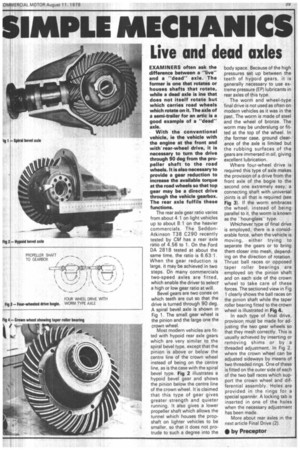
Bevel gears are two cones on which teeth are cut so that the drive is turned through 90 deg. A spiral bevel axle is shown in Fig 1. The small gear wheel is the pinion and the large one the crown wheel.
Most modern vehicles are fitted with hypoid rear axle gears which are very similar to the spiral bevel type, except that the pinion is above or below the centre line of the crown wheel instead of being on the centre line, as is the case with the spiral bevel type. Fig 2 illustrates a hypoid bevel gear and shows the pinion below the centre line of the crown wheel. It is claimed that this type of gear gives greater strength and quieter running. It also gives a lower propeller shaft which allows the tunnel which houses the prop shaft on lighter vehicles to be smaller, so that it does not protrude to such a degree into the body space. Because of the high pressures set up between the teeth of hypoid gears, it is generally necessary to use extreme pressure (EP) lubricants in rear axles of this type.
. The worm and wheel-type final drive is not used as often on modern vehicles as it was in the past. The worm is made of steel and the wheel of bronze. The worm may be underslung or fitted at the top of the wheel. In ,the former case, ground clearance of the axle is limited but the rubbing surfaces of the gears are immersed in oil, giving. excellent lubrication.
Where four-wheel drive is required this type of axle makes the provision of a drive from the front axle of the bogie to the second one extremely easy; a connecting shaft with universal joints is all that is required (see Fig 3). If the worm embraces the wheel, instead of being parallel to it, the worm is known as the -hour-glasstype.
Whichever type of final drive is employed, there is a considerable force, when the vehicle is moving, either trying to separate the gears or to bring them closer into mesh, depending on the direction of rotation. Thrust ball races or opposed taper roller bearings are employed on the pinion shaft and on each side of the crown wheel to take care of these forces. The sectioned view in Fig 1 clearly shows the ball races on the pinion shaft while the taper roller bearing fitted to the crown wheel is illustrated in Fig 4.
In each type of final drive, provision, must be made for adjusting the two gear wheels so that they mesh correctly. This is usually achieved by inserting or removing shims or by a threaded adjustment. In Fig 2, where the crown wheel can be adjusted sideways by means of two threaded rings. One of these is fitted on the outer side of each of the two ball races which support the crown wheel and differential assembly. Holes are provided in the rings for a special spanner. A locking tab is inserted in one of the holes when the necessary adjustment has been made.
More about rear axles in the next article Final Drive (2).