


Transport of Drums
Page 74
If you've noticed an error in this article please click here to report it so we can fix it.
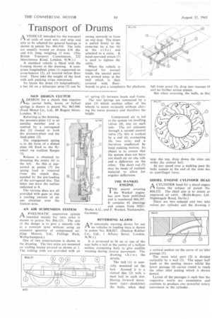
AVEHICLE intended for the transport of coils of steel wire and strip and able to he adapted for general haulage is shown in patent No. 866,910. The coils are usually wound on drums 6-ft, dia. and 4-ft. long, weighing 15 tons. (The British Transport Commission, 222 Marylebone Road, London, N.W.1.) A standard vehicle is fitted with the framing shown in the drawing, it comprises longitudinal joists (1) supported on cross-bearers (2), all located below floor level. These take the weight of the load with soft packing strips interposed.
To locate the drum (3) longitudinally, a bar (4) on a telescopic prop (5) can be
NEW DESIGN CLUTCH ADESIGN for a dutch that requires no carrier bolts, levers or helical springs is shown in patent No. 865,948. (Ford Motor Co., Ltd., 88 Regent Street. London, W.1.)
Referring to the drawing, the pressure-plate (1) is an annular member and is centred by a corrugated disc (2) riveted to both the pressure-plate and the back-plate (3).
The engagement spring is in the form of a dished plate (4) fixed to the flywheel via resilient flanges (5).
Release is obtained by thrusting the centre (6) to the left. As this is supported at points (7) the spring load is removed from the clutch 'disc, assisted by the pre-loading of the corrugated disc. The latter can have the outline indicated at 8.
The various discs are all provided with gaps so that a cooling current of air can circulate over the friction area.
AN AIR SUSPENSION SYSTEM
A PNEUMATIC suspension system intended mainly for twin aides is shown in patent No. 866.121. The aim of the design is to give a smooth ride at a constant level without using an excessive quantity of compressed air. (Guy Motors, Ltd., Fallings Park, Wolverhampton.) One of two constructions is shown in the drawing. The two axles are mounted on trailing beams pivoted as shown at 1. The trailing ends are provided with an
swung upwards to form an end stop. The drum is pulled firmly to the cross-bar by a bar (6) at the other end attached to a cable.. A hand-operated winch (7) is used to tighten the cable.
When the vehicle is required for normal loads, the special parts are stowed away in the well which is then covered with floorboards to give a completely flat platform.
air spring (2) between beam and frame.
The two springs are connected by a pipe (3) which enables either of the wheels to move vertically without altering the mean pressure and therefore the height.
Compressed air is led to the system via levelling valves (4), one on each side. The air exhausts through a second control valve (5); this is worked by a rod (6) connecting the two axles and is therefore unaffected by local rocking motion. Its object is to ensure that the system does not have too much air on one side and a deficiency on the other. The short rod (7) may be made of resilient material to allow for angular deflections.
THE WANKEL ENGINE
THE patent covering
the Wankel engine has now been published and is numbered 866,307. It contains 42 drawings and comes from NSUWerke A.G., and F. Wankel, Neckarsulm, Germany.
REVERSING ALARM
AN automatic warning device for use on vehicles in loading bays is shown in patent No. 868,027. (Dunlop Rubber Co., Ltd., I Albany Street, I.ondon, NW.].)
It is proposed to fit on to one of the rear hubs a bell in the centre of a hollow section containing balls to give audible warning during reverse movement. The drawing shows the details.
The bell (1) is centrally mounted on the hub. Around it is a slotted disc (2) with a steel ball in each slot. During forward movement (anticlockwise) the balls, when they
fall from point (3), drop into recesses 14 and no further action ensues.
But when reversing, the halls, as the
near the top, drop down the slots anc strike the central bell.
At any speed over a walking pace tht balls remain at the end of the slots duc to centrifugal force.
DIESEL ENGINE CYLINDER HEAD
ACYLINDER head for a diesel engine forms the subject of patent No 868,525. The chief aim is to create an improved air swirl. (Rolls-Royce, Ltd. Nightingale Road, Derby.)
There are two exhaust and two inlet valves per cylinder and the drawing i!
a vertical section on the curve of an inlet passage (1).
The main inlet port (2) is divided vertically by a wall (3). The upper half leads to the seating shown whilst the lower passage (4) curves round to reach the other inlet seating which is shown dotted.
Layout of the passages is such that the respective swirls are cumulative and combine to produce one powerful rotary movement in the cylinder.