


Coil ignition, 2
Page 46
If you've noticed an error in this article please click here to report it so we can fix it.
THE LAST article (CM, Febry 28) a coil ignition system a single-cylinder engine was cribed, but in most cases r-, sixor even eight-cylinder 3ines are used in motor ides and means have to be vided to distribute the highion (HT) current to each cyl
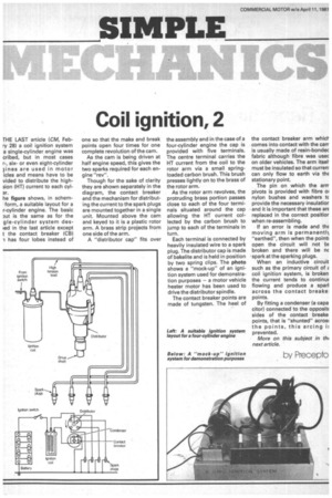
he figure shows, in schemform, a suitable layout for a r-cylinder engine. The basic )ut is the same as for the gle-cylinder system desled in the last article except t the contact breaker (CB) -1 has four lobes instead of
one so that the make and break points open four times for one complete revolution of the cam.
As the cam is being driven at half engine speed, this gives the two sparks required for each engine "rev".
Though for the sake of clarity they are shown separately in the diagram, the contact breaker and the mechanism for distributing the current to the spark plugs are mounted together in a single unit. Mounted above the cam and keyed to it is a plastic rotor arm. A brass strip projects from one side of the arm.
A "distributor cap" fits over the assembly and in the case of a four-cylinder engine the cap is provided with five terminals. The centre terminal carries the HT current from the coil to the rotor arm via a small springloaded carbon brush. This brush presses lightly on to the brass of the rotor arm.
As the rotor arm revolves, the protruding brass portion passes close to each of the four terminals situated around the cap allowing the HT current collected by the carbon brush to jump to each of the terminals in turn.
Each terminal is connected by heavily insulated wire to a spark plug. The distributor cap is made of bakelite and is held in position by two spring clips. The photo shows a "mock-up" of an ignition system used for demonstration purposes — a motor vehicle heater motor has been used to drive the distributor spindle.
The contact breaker points are made of tungsten. The heel of
the contact breaker arm which comes into contact with the carr is usually made of resin-bondec fabric although fibre was usec on older vehicles. The arm itsel. must be insulated so that curreni can only flow to earth via thE stationary point.
The pin on which the arrr pivots is provided with fibre oi nylon bushes and washers tc provide the necessary insulatior • and it is important that these arE replaced in the correct positior when re-assembling.
If an error is made and thE moving arm is permanent!) "earthed", then when the point; open the circuit will not bE broken and there will be nc
• spark at the sparking plugs. When an inductive circuit such as the primary circuit of (. coil ignition system, is broken the current tends to continuE flowing and produce a sparl across the contact breake, points.
By fitting a condenser (a capa citor) connected to the opposit( sides of the contact breake points, that is "shunted" acrom the points, this arcing prevented.
More on this subject in the next article.
oy Precepto