


An Unusual Engine Mounting
Page 48
If you've noticed an error in this article please click here to report it so we can fix it.
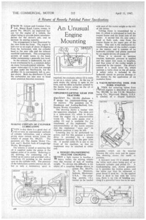
FROM W. Limon and Commer Cars, Ltd., Biscot Road, Luton, comes, in patent No. 584,237, an improved layout tor the engine of a vehicle, the object being to provide better accommodation for the driver's cab, and to increase its seating capacity.
The arrangement is best illustrated by the view from the front. The engine is laid over at an angle of about 24 degrees from the horizontal, with the cylinder head to the near side and the exhaust manifold underneath. This arrangement permits of ready access to the head, whilst maintaining a generally low level.
As the exhaust is underneath, the cab is not overheated by it, a common defect on many forward-control vehicles. The upper water-pipe (1) is just low enough to pass under the floorboards, but the oil-filler (2) is conveniently left to project above. Both the distributor (3) and the carburetter are also near to hand when attention becomes necessary MAKING CERTAIN OF CYLINDER LUBRICATION
EVEN to-day there is a good deal of hit-or-miss in conventional methods of cylinder lubrication, and a scheme giving more certain action forms the
subject of patent No. 584,225. The patentees are The Austin Motor Co., Ltd., and J. Haefeli, both of Longbridge Works, Birmingham.
The scheme is 'aimed at ensuring that oil is supplied under the piston at the highest point of its stroke. Referring to he drawing, the connecting rod is :trilled up its centre and provided with a :Toss-bore (1) pointing to the desired spot on the cylinder wall. The pressure f the lubrication system conveys the oil, but as only a momentary spurt is
required, the crankpin oilway (2) is made to act as a rotary valve. At the top of each stroke the oilway is open to the bore, and the effect is further assisted by the inertia forces acting on the oil at the moment of reversal.
IMPLEMENT-LIFTING GEAR FOR TRACTORS
DATENT No. 583.920 discloses a
design for implement-lifting gear for tractors. The patentees are NV. Henderson and Aveling-Barford, Ltd., Invicta Works, Grantham.
The drawing shows a tractor with the apparatus attached. The niain unit is a cable-drum (1), which is driven from the engine via a non-reversible worm (2). The cable passes over a pulley (3) and is available for the attachment of the implement. The non-reversibility of the worm ensures that the implement "stays put" in whatever position it may be left.
Lowering has to be performed by power, and for this purpose a reverse drive is provided by a simple mechanism operated by the gear lever (4). A second cable (5) is run to the front of the machine, so that an implement may be attached at either end.
A WEIGHT-TRANSFERRING TRACTOR COUPLING
WHEN a light tractor is hauling a heavy trailer, the driving wheels may slip because of lack of loading weight. To obviate this difficulty is the object of a coupling linkage shown in patent No. 583.976, by L. Simmons, Jackson, Mississippi, U.S.A. The coupling permits t h e tractor to be loaded
with part of the trailer weight at the will of the driver.
Towing force is transmitted by a link (1) which is articulated to both the tractor frame and the front axle of the trailer. A second link (2), also articulated at both ends, runs from the tractor frame to the upper part of the trailer. This unit is the mechanism for transferring some of the trailer's weight to the tractor, and it consists of an hydraulic cylinder and piston operated by an engine-driven oil pump (3).
When it is desired to Increase traction, hydraulic pressure is applied and the upper link tends to lengthen, and thus some of the trailer weight is supported by the tractor. The driver's control is a small lever (4), which operates a valve close to the oil pump. A safety valve is included in the hydraulic circuit to prevent damage to the tractor by the application of an excessive force.
A VALVE-REMOVING TOOL FOR FORD ENGINES
A TOOL for removing valves from riFord engines is described in patent No. 583,340, by the T.C.M. Manufacturing Co., Maywood, Illinois, U.S.A. It consists of a shaped hydraulic
expander, which can be inserted between the valve stem and its tappet. The drawing shows the outfit in position.
A two-part nose (1) is placed under the valve, each Piece being part of an hydraulic cylinder and piston (2). A hand-pumping unit, shown generaily at 3, provides the motive power, and the valve can thus be subjected to great thrust if need be. As the applied force is dead in line with the valve axis, there is no risk of bending anything if a powerful force has to be used.