


Patents Completed.
Page 22
If you've noticed an error in this article please click here to report it so we can fix it.
Complete specifications of the following patents will be sent to any address in the United Kingdom by the Sale Branch, Patent Office, Holborn, W.C., upon receipt of eightpence per copy.
A Change-Speed Control.
W. and G. Du Cros, Ltd., and D. G. Snodgrass.—No. 21,505, dated 20th September, 1911.—In this specification there is described a lever operating on the gate-change principle for a change-speed gear. As heretofore constructed, the hand-lever has been moved sideways parallel to itself, or tilted, or moved in a longitudinal direction. According to the present invention the lever is rotated on its longitudinal axis to enable an extension of it to be moved from one gate to another. On the lower end of the lever is secured a frame, which is pivoted by trunnions in the longitudinal axis of the lever. The frame carries an extension• piece which projects towards the left, and lies opposite a flange secured on the inside of the casing. This flange has an opening about half-way up, through which the projection can pass as the lever arid frame are rotated. Two arms which are connected to the gear-wheels are engaged by the frame, which in its mid•position holds both from movement. On turning the lever either one or other of these arms is released from engagement with the frame, and allows the corresponding gears to be nperatedSuitablc locking gear is provided to hold the parts in the various operative positions.
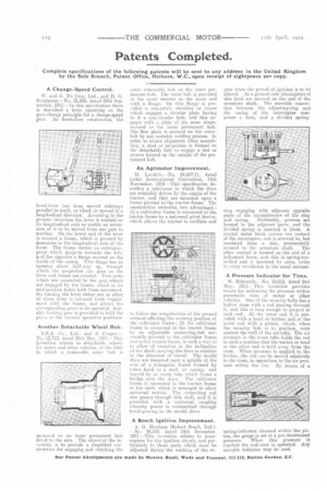
Another Detachable Wheel Hub.
R.S.A. Co., Ltd.. and S. Cooper.— No. 12,712, dated 26th May. 1911.-ThiA invention relates to detachable wheels for motor and other vehicles, of the kind in which a removable outer hub is mounted on an inner permanent hub fitted to the axle. The object of the invention is to provide a simplified construction for engaging and clutching the
outer removable hub on the inner permanent hub. The outer hub is provided in the usual manner at the inner end with a flange. On this flange is provided a concentric shoulder or recess which engages a circular plate having in it a non-circular hole, and this engages with a plate of the same shape, secured to the inner permanent hub. The first plate is secured on the outerhub by any suitable welding process. In order to secure alignment when assembling, a stud or projection is formed on the detachable hub to engage a slot or groove formed on the outside of the permanent hub.
An Agrimotor Improvement.
M. Landrin.—No. 24,667;1E, dated under International Convention, 19th November, 1910.—This specification describes a cultivator in which the discs are rotatablv driven by the engine of the tractor, and they are mounted upon a frame pivoted to the tractor frame. The construction embodies two advantages : (1) a cultivator frame is connected to the tractor frame by a universal pivot device, which allows the tractor to oscillate and to follow the irregularities of the ground without affecting the working position of the cultivator frame ; (2) the cultivator frame is connected to the tractor frame by an adjustable connecting-rod universally pivoted to the cultivator frame and to the tractor frame, in such a way as to allow of variation in the inclination of the shaft carrying the discs in relation to the direction of travel. The mould discs are mounted upon a spindle at the rear of a triangular frame farmed by tubes fixed to a shell or easing, and braced by an extra tube which, forms a bridge over the discs. The cultivator frame is connected to the tractor frame at the shell, which is arranged to allow universal motion. The connecting rod also passes through this shell, and it is provided with a universal coupling whereby power is transmitted through bevel-gearing to the mould discs.
A Bosch Ignition Improvement.
A. G. Blotham (Robert Basch, -Ltd.). -No. 28,518, dated 1.8th December, 1911.—This invention relates to interrupters for the ignition circuit, and particularly to those parts which must be adjusted during the working of the en
gine when the period of ignition is to be altered. As a general rule interrupters of this kind are secured on the end of the armature shaft. The movable connection between the adjusting-ring and the casing of the interrupter comprises a bent, and a divided spring.
ring engaging with adjacent opposite parts of the circumference of the ring and casing. Preferably, grooves are formed in the adjacent parts, and the divided spring is inserted in them. A central metal block carries one contact of the interrupter, and is screwed to, but insulated from a disc, permanently secured to the armature shaft. The other contact. is formed on the end of a bell-crank lever, and this is spring-controlled and is operated by corns, twice in every revolution in the usual manner,
A Pressure Indicator for Tires.
Edmunds.—No. 10,612, dated 2nd May, 1911.-This invention provides means for indicating the pressure within pneumatic tires of motor or other vehicles. One of the security bolts has a hollow stem with a. rod passing through it, arid this is long enough to project at each end. At the outer end it is provided with a head or button and at the inner end with a piston, which, when the security bolt is in position, rests against the wall of the air-tube. The air pressure in the inner tube holds the rod in such a position that the button or head at the other end is held away from the stem, 117C-Inni pressure is applied to the button, the rod can be moved relatively tu the stem, in opposition to the air pressure within the tire. By means of a
spring-indicator situated within the piston, the gauge is set at a pre determined pressure. When this pressure is reached the indicator is operated. Any suitable indicator may be used.