


An Inlet and Exhaust Valve Unit
Page 58
If you've noticed an error in this article please click here to report it so we can fix it.
DATENT No. 712,780 shows a
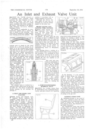
combined valve assembly which performs the dual function of inlet and exhaust valves. The aim is to obtain a large valve area in a small space, combined with better cooling of the valves. The patentee is M. Bolton, 2369 .Prinecton A venu e, Berkley, Michigan, U.S.A.
The scheme isapplicable to overhead-valve engines and a section of one is shown in the drawing. The valve pair is located in a single coaxial bore running across the cylinder. The exhaust port is closed in the usual manner by a valve (1) seating on an insert (2) in the cylinder-head casting. The head of the valve is double-edged and• seats also on the end of .a pistonlike sleeve (3) which communicates with the inlet port (4). The sleeve is worked after the manner of a valve by. a rocker. •(5) against return springs (6), the operating rod (7) passing throud the tubular exhaust valve. The combustion space . (8) has an arch-shaped outline, surrounding the duplex . valve and widening out at point 9over the cylinder space.
When the sleeve is moved to the right it opens the inlet passage while the exhaust Valve. remains on its seat. When the exhaust valve moves to the right, it opens its own port and at the same time pushes the inlet sleeve to the right, maintaining closure as it does so, •
The exhaust valve is worked by a separate rocker which bears on the face of collar 10. The sleeve is lubricated during running by oil arriving via passage 11.
A SEAT FOR BUSES AND COACHES
FROM Aceles and Pollock, Ltd., Paddock Works, Oldbury, Birmingham, comes patent No. 712,715, dealing with the design of seats for public service vehicles. Designers are continually demanding lighter seats and according to the patent the limit has been reached in lightening the frame. The next weight saving has therefore to be made with the cushions.
To this end, the frame is made from tube to the outline shown. The seatsupporting tubes (1) are curved, so that the cushion can be of uniform thickness instead of being thick in the middle as is usual. This is said to make a worthwhile saving in weight. The thin
A40
cushion is provided with a simple backing of plywood.
Although not shown, the back squab (2) may also be mounted on a curved tubular support in the same way.
BRAKE FACING CONTAINING WIRE NETTING IkAANY brake facings are al reinforced with some form of wire mesh, but according to patent No. 712,469, they suffer from certain defects. In many cases the wire is springy, so that it is difficult to bend to a desired radius; also, if a piece he cut from the sheet as is often done, the wires tend to fray and work out. A scheme claimed to be superior in these respects is shown in the patent by Drahtwerk Josef Roesler K.-G., 14 Opmiinderweg,--Soest in Westphalia, Germany.
The drawing• shows a section of a motor-vehicle brake facing according to this invention. It is proposed to form a mesh not by weaving but by laying the woof wires (I) on the warp (2) and welding the two sets together at all points of contact
Soft steel wire possessing no springiness is used, and the welding ensures that no matter where the sheet be cut, no loose ends can emerge. A further feature of the invention is that the wire netting is composed of uncoated and, particularly, nongalvanized iron or steel wires. An earlier patent, number 707,267, describes the machine used for welding the wires.
A SURFACE-DISCHARGE SPARKING PLUG
PATENT No. 713,006, comes from Rolls-Royce, Ltd., Nightingale Road, Derby, and gives details of a sparking
plug of the surface-discharge type. This operates by creating a glow or arc condition across a narrow gap on the surface of a semi-conductor.
With plugs of this type, should thermal expansion cause a small air-gap to form in the circuit, the plug would cease to function as the applied voltage is quite low. It is to deal with this problem that the present scheme was designed.
In the drawing, 1 is the insulator which is faced across the lower end with a layer of semi-conducting material. The central electrode is in the form of a bolt and is tightened so that its tip (2) presses firmly into the semi-conductor. Similarly, the sharp edge (3) of the outer shell is pressed into firm contact by the nut 4.
To deal with thermal expansion, the nut actually transmits its force through a spring washer (5) which ensures good contact at all times. These sharp-edged contacts perform the additional function of acting as the gas seal,
KEEPING TYRES COOL
AMODIFICATION to the tread of a tyre, claimed to have the effect of keeping down its temperature in use, comes in patent No, 712,339 (Peters Pneu Renova KG., Bad Homburg ver der Hobe, Germany).
The speeification states that during running, heat is generated mainly in the thickest parts of the tread and in the proposed tread pattern the thick shoulder portion is undercut as shown at 1. The undercut may be provided with ribs (2). In that event, the ribs must have connecting holes (3) passing through them to afford a complete air passage around the tyre.