


A Differential Capable of Unequal Torque Distribution
Page 64
If you've noticed an error in this article please click here to report it so we can fix it.
N/TUCH interest seems to be arising aliu the problem of designing a differential which will allow a slow variation in the wheel speeds, but which will prevent a large discrepancy, as in the case of one wheel spinning when momentarily relieved of its load. A scheme of this description forms the subject of patent No. 469,621, by F. Lawler, 251, Kearny Street, San Francisco, U.S.A.
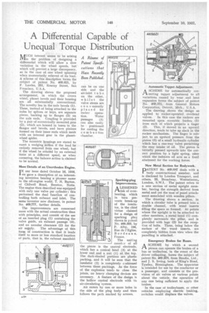
The drawing shows the proposed arrangement, in which the crown wheel, planet bevels and their housing are all substantially conventional. The novelty lies in the axle bevels (1). These, instead of being attached to the axles by splines or keys, are separate pieces, backing up to flanges (3) on the axle ends. Coupling is provided by a pair of eccentrically mounted pins (2), which are housed in bores in the flanges and bevels, and have pinions formed on their inner ends which mesh with an internal gear in the planetwheel spider.
The eccentric housings are stated to exert a wedging action if the load be entirely removed from one wheel, but if the wheel be rotated by an external force at a different speed, as when cornering, the balance action is claimed to be normal.
More Details of an Unorthodox Engine.
TN our issue dated October 16, 1936, 1 we gave a description of an interesting invention bearing a pioneer name in the oil-engine world, T. H. Barton, of Chilwell Road, Beeston, Notts. The engine then described was equipped with only one valve per cylinder ; this performed the dual function of controlling both exhaust and inlet. The same inventor now discloses, in patent No. 469,777, further details.
The improvements are concerned more with the actual construction than with principles, and consist of the use of an inserted plug (1) containing the valve guide, an exhaust passage (4), and an annular clearance (2) for the air supply. The advantage of this form of construction is that it lends itself to more or less standard location of parts, that is, the exhaust manifold Sparking-plug Improvements.
A LESSENED .1-1risk of overheating, which in turn prevents break-up of the insulator, is the chief virtue claimed for a design of sparking plug shown in patent No. 469,565, by P. Alby, 196, Rue de l'Eglise, 2 Bordeaux, France.
3 The uniting memle-r of all the pieces is the central electrode, which has a conical head (3) at the lower end and a nut (1) at the top. The dark-shaded portions are plastic packing, and it will be seen that the insulator (2) is completely ceshioned between these packing's. As the force of the explosion tends to close the joints, no heavy clamping devices are necessary. A feature of the design is the hollow central electrode with its air-circulating system.
Air enters by one or more holes in the side of the plug body and then follows the path marked by arrows. Automatic Tappet Adjustment.
A SCHEME for automatically corit meting tappet adjustment to all variations caused by wear and heat expansion forms the subject of patent No. 469,372, from General Motors Corporation, Detroit, Mich., U.S.A.
The drawing shows the design as applied to rocker-operated overhead valves. In this case the rockers are mounted upon eccentric bushes (1) from each of which projects a finger (2). This, if moved in an upward direction, tends to take up slack in the rocker mechanism. The finger is subject to an upward pressure from the piston (3) of a small hydraulic cylinder which has a one-way valve permitting the easy intake of oil. The piston is initially pressed upwards into the correct position by a light spring, aster which the indrawn oil acts as a fixed abutment for the working forces, New Metal Section for Bodywork.
PATENT No. 469,687 deals with a body constructional member, and is disclosed by London Transport, and others, 55, Broadway, Westminster, London, S.W.1. The patent refers to a new section of metal upright member, having the strength derived from metal and yet the ease of panel attachment associated with wooden pillars.
The drawing shows a section, in which a circular tube is pressed into a double channel, with wood inserts filling the space so formed. At points where the upright is to be attached to other members, a metal band (1) completely surrounds the pillar, and is provided with lugs (2) for the reception of bolts. These, being below the surface of the wood inserts, are completely hidden from view when the panelling is attached.
Emergency Brakes for Buses.
ASCHEME by which a second person can operate the brakes of a bus or trolleybus, in the event of the driver collapsing, forms the subject of patent No. 469,67, from Bendix, Ltd., and j. S. Irving, both of King's Road, Tyseley, Birmingham. The apparatus is intended for use by the conductor or a passenger, and consists ol the provision of air valves at various points about the vehicle, the operation of any one being sufficient to apply the brakes.
In the case of trolleybuses, or other vehicles employing electric braking, switches would displace the valves.