


AN ENGLISH-MADE OLSON CONVERSION UNIT.
Page 11
If you've noticed an error in this article please click here to report it so we can fix it.
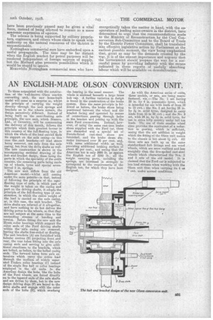
To those acquainted with the construction of the well-known Olson one-ton converting unit, the new home-built model will come as a surprise as, whilst the principle of carrying the weight directly through the unit. springs and brackets on to the wheels remain, the design issentirely different. Instead of being built on the semi-floating axle principle, the new unit, which Brame°, Ltd., of Coventry, will be commencing the delivery of this month, follow a the principle which finds greatest favour in this country of the full-floating type in which the whole of the load carried finds its support on the axle casing—in this case the tunit brackets—all load stress being removed, not only from the axle casing, but from the drive shafts as well. The new construction is shown in the , accompanying sectional drawing of the hub and _bracket design, these being the parts in which the speciality of the outfit consists, the remaining parts being made up of wheels, tyres and special sevenleaved 2 in. springs. The new unit differs from the old , American model—whilst still coming under \ the same patents—in that, instead of following the principle of the seimifloating type of axle, in which part of the weight is taken on the casing and part on the driving shafts, it adopts the principle of the full-floating type of construction, in which the entire weight of the load is carried on the axle casing, or, in this case, the unit bracket. The drive shafts are relieved of it altogether, and have nothing to do but deliver the driving power to the wheels, so that they are not subject at the same time to the contending stresses of bending and torsion. Before fitting the new unit the Hyatt roller bearings which support the outer ends of the Ford driving shafts within the axle casing are removed, leaving the shafts free-ended or floating. The unit brackets (A) are furnished with tubular centres (B) projecting front and rear, the rear tubes fitting into the axle casing ends and serving to give additional steadiness to the brackets, which are bolted, as before' to the belled casing ends. The forward tubes form axle extensions which carry the entire load through the medium of widely separated Timken roller bearings (C) instead of the single line ball or roller bearings employed in the old units. In the American design the hubs, like the hubs of the Ford wheels are forced directly on to the tapered ends of the axle shafts and are driven by them, but in the new design driving dogs (F) are keyed to the drive shafts and engage with the outer ends of the hubs (E), which overhang the bearing in the usual manner. The whole is enclosed beneath a large brass hub cap. A further variation in design is found in the construction c,f the brake system. Here the same principle is followed as before, the brake shoes being positioned between the wheel and the bracket facing and operated by means of connections passing through holes in the bracket and joining up with the main Ford connections. Instead, however, of usingthe same cast-iron brake shoes supplied with the Ford car, these are discarded and a special set of Ferodo-faced cast-steel shoes are furnished, and the brake drum diameter increased over 30 per cent. and, with some additional width as well, providing additional braking surface of about 40 per cent. and seeing that the American ton is only 2000 lb. as against the English ton of 2240 lb., all the weight carrying parts, including the springs, are increased in strength to correspond to the requirements of the English ton, for which they have been designed. As with the American series of units, three models, or sets, are being manufactured, viz. :—The No. 1 set having 28 in. by 4 in. pneumatic tyres, which is intended for use with loads of front 10 to 15 cwt.; the No. 2 set laving 28 in. by 3 in. solid tyres, designed to carry loads from 15 to 20 cwt.; and the No. 3 set, with 24 in. by 3 in. solid tyres, for use in extra hilly country under full ton loads. The use of thelie smaller wheel sizes provides the equivalent of a reduction in gearing, which is sufficient, seeing that the net addition in weight which the fitting of the Olson unit makes to the chassis is but about 1 mit. All three sets are built up on the same standardized hub fittings and use wood wheels, which are more resilient and less unsightly than the five-spoked cast-steel wheels which characterized the 'Nos. 2 and 3 sets of the old model. It is claimed that the Ford car is subjected to less load stresses when working with the Olson unit than when carrying its 6 or 7 cwt. under normal conditions.