


Patents Completed.
Page 26
If you've noticed an error in this article please click here to report it so we can fix it.
Transmission Gear.
V. Lancia, No. 12,493, dated 25th May, 1912.— This invention is particularly applicable to chassis in which the change. speed gear is arranged on the rear axle ; it has for its object to connect the rear axle rigidly to the clutch, so preventing undesirable oscillations which may occur when the machine is running over rough ground. The flywheel, shown towards the left of the figure, is connected to the clutch through a cardan joint so that the clutch may be rigidly connected to the shaft transmitting the drive to the change-speed gear. This shaft is enclosed in a radius rod which is forked at one end and is connected to the chassis. The shaft, therefore, is rigid, and forms a single piece between the change-speed gear and the clutch.
A New Valve Gear.
H. C. Dupuis, No. 16,953, dated 24th July, 1911.—According to this invention the inlet and exhaust to and from the cylinder are controlled by a sliding-sleeve enclosing a valve. This valve receives both a rotary and a reciprocating motion, and it takes the form of a hollow cylinder having a cut-away portion. The engine cylinder and the sleeve, are provided with ports for inlet and exhaust, and the valve is also supplied with a port adapted to register with the inlet ports in the sleeve and engine cylinder. The entering mixture is fed through the interior of the valve, and thence through its port into
the engine cylinder, while, for exhaust, the valve is rotated so that its cut-away portion comes opposite the registering parts in the sleeve and the engine cylinder. Several modifications are described.
New Albion Valve.'
Albion Motor Car Co., Ltd., and T. B. Murray, No. 24,705, dated 7th November, 1911.—This specification describes valves for four-stroke cycle engines which are so operated that large port areas can be rapidly opened and closed. At the side of the engine cylinder the valves are arranged inside a fixed ported liner. The valves consist of an unported piston valve and_a sleeve valve, one end of the
piston valve being reduced in diameter to reciprocate in the sleeve valve. Suitable eccentrics operated by a half-speed shaft are provided to work the piston and sleeve valves. The relative angular relation of the operating eccentrics is adjusted to ensure proper co-operation of the two valved.
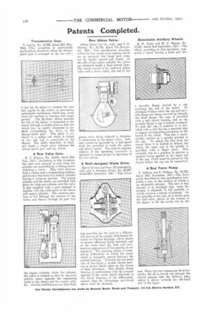
A Well-designed Worm Drive.
David Brown and Sons (Huddersfield), Ltd., and S. Bramley-Moore, No. 29,247. dated 29th December, 1911.—This inven
tion provides for the load in a differential gearing to be equally distributed between two thrust bearings, which allows of greater efficiency being obtained, and at the same time the neat and symmetrical appearance of the gearing is not impaired. The drawing shows a wormdrivers differential in which the worm wheel is unequally spaced between the journal bearings. Towards the left-hand side of the figure a double thrust bearing is shown which takes up the thrust in both directions. This double thrust bearing, in combination with the unequal spacing of the worm wheel relatively to the thrust bearings of the differential. ensures that the advantages mentioned above shall be obtained. Detachable Artillery Wheels.
E. H. Jones and H. C. Baines, No. 19,591, dated 2nd September, 1911.—The wheel, according to this invention, comprises a barrel having a fixed and also
a movable flange carried by a cap enclosing the end of the barrel. To eliminate friction when the cap and movable flange are being screwed up towards the fixed flange, the cape is provided with a ball thrust bearing, and on the movable flange a cap is loosely arranged. To lock the cap in position it is provided with a disc having a serrated edge to engage corresponding serrations on the barrel of the wheel. This disc is eccentrically carried on a spindle pivoted in the cap. To unlock the disc from the barrel when it is desired to detach the wheel, the outer end of the spindle is provided with a finger piece. This normally lies in a position to prevent a spanner being applied to the outer end of the cap, which must be moved by the fingers before the cap can be unscrewed.
A New Force Pump.
T. Oldham and F. Oldham, No. 25,735, dated 18th November, 1911.—The force pump described in this specification comprises a ram, in the interior of which is an adjustable plunger. The end of this plunger is so arranged that, when the plunger is adjusted, it will partially or wholly uncover a lateral oil passage. On the upstroke of the ram, oil is drawn past the ball-valve, shown at the bottom of the figure, to fill the cavity left by the ram. When the ram commences its downstroke, the oil is forced out through the lateral passage into the delivery pipe, which is shown towards the left-hand side of the figure.