


TRAILER BRAKE GEAR.
Page 32
If you've noticed an error in this article please click here to report it so we can fix it.
A Résumé of Recently Published Patents.
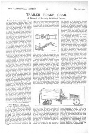
In view of the concern which is being shown, in some quarters here, over the more stringent attitude which the authorities are adopting in connection with trailers not fitted with efficient brakes, it is of interest to note that in the United States, which has hitherto been a land of almost perfect freedom as regards the use of motor vehicles of air kinds, regulations are being fOimulated which have as their object the provision of effective brakes on all trailers, the said brakes to be operated either by the driver of the towing vehicle or by some assistant carried on the trailer or trailers. The Raybestos Co., of America, in their preliminary remarks in connection With patent No. 155,219 draw attention to this, and to the disability under which motor haulage will suffer if it becomes necessary to have a man on each trailer as well as the driver for the vehicle itself. In the specification to which we refer, they describe a compensating gear by means of which the, brakes on one or more trailers can be operated simultaneously and by the same hand lever as that. on the motor vehicle.
The chief feature of the invention is a compensating bar, which is disposed normally parallel to the front end of the trailer to which it is freely pivoted at one end, the pivot being free to slide in a longitudinal slot in bracket attached to the trailer itself. The two ends of this bar are coupled be universally jointed rods to the rear axle of the towing vehicle and to the front axle of the trailer respectively. In cases where more than one trailer is used, a similar bar could be attached in the same manner to the front end of each trailer, and could be coupled correspondingly to the rear axle of the trailer in front and to the front axle of the'trailer by which it was carried. Two bell crank levers are carried on this compensating bar with their fulcra cornpiratively near together and dose to the centre of the bar. The short arms of these levers are coupled together. The ends of the long arms communicate one with the brake gear on the lorry, the other with the brake gear
on the trailer. With the lorry and trailer in correct alignment, the operation of the brakes is direct. A pull on the main brake lever operates the brakes on the lorry, fled, through the double bell crank lever, those on the trailer, Any variation in alignment in any direce then between lorry and trailer is corrected by this compensating bar, which carries the brake operating gear with it in such a way that the lack of alignment does not at. all affect their operation.
Other Patents of Interest.
A rather ingenious vacuum cleaner for the road is the subject of No. 160,533, by W. J. Cowell. The lorry carries a Large tank, from this at the rear depends a flexible pipe, the lower end of which is quite close to the surface of the road. This pipe is continued inside the tank, and, in one portion of its length, is fitted with a venturi orifice, through which air is blown by an enginedriven fan, thus creating E. suction effect in the downwardly depending exterior pipe and.causing it to pick up from the road, and transfer to the interior of the
1336 tank, an' dirt or impurities which may come in its way. Once inside the tank, the inrush ing air and the refuse which it carries, may be either baffled or passed through water or disinfectant, or other
wise treated so that it deposits the impurities which have been picked up from the road. It then passes out through a vent-hole in the top of the tank. Beneath the vehicle, behind the rear axle, and disposed at an acute angle to the axle, are two sweeping brushes, slightly conical, tapering from their onesides towards the centre of the lorry, where they meet. They are driven by bevel gearing off the wheels of the lorry, and may be lifted out of contact with the road when not required. The operation of lifting automatically disconnects the driving gear of the brushes. It is claimed that these brushes, partly on accountof their disposition, and partly because of their taper form, collect the dirt on the road and leave it in a thin stream beneath the vacuum pipe.
-No. 160,720, by C. Pearso. describes 9. method of constructing a cheap motor body which is rapidly convertible from a platform lorry to a passenger vehicle,
and vice versa. The seats are disposed along the side dl the body, and are hinged at their front edges, so that they will fold over and drop down into the well. When so disposed the undersides of these seats and that portion of the body in which they were resting, present a plain platform. The backs of the seats rest on the bottom of the well, and serve as an additional support for the platform. A flexible guard for use between a tractor and a trailer is the subject of N. 160,498, by F. R. Hardy. Several constructions are described andillustrated in the specification. Tha principle is that of a quickly extensible light framework his to a support beneath the rear end of the tractor, and adapted to be coupled to a similar support, depending from the front end of the trailer. There are naturally two. guards, one at each side, and when not in use these guards fold up compactly beneath the bodywork of the tractor. .
An ingenious fuel pump for transferring petrol from the rear tank of an automobile to, presumably, an auxiliary gravity tank near the engine, is described by P. Fisch and another in specification No. 155.203. A vertical tube is suspended in the petrol tank; its lower end reaches nearly to the bottom of the tank itself and is fitted with a ball valve. A loosely fitting ram inside this tube is operated by a flexible lever fulcrumed on the tank, and operated upon by the rear axle as it moves up and down under the influence of the road, springs. There is another ball valve which acts as a, delivery valve, and communication between the pump and carburetter or auxiliary. tank is by means of the usual copper pipe. The difficulty of lubricating overhead' valve gear and at the same time preventing waste of lubricant is surmounted by a method which is described in No. 143,898, by the Daimler Motoren Gesellschaft. The overhead camshaft is contained as usual in a cylindrical casing Which eiitends over the whole engine. The lever, which is operated by the cam, is mounted upon and keyed to a shaft which projects through an oiltight bearing to the exterior of the casing, where it receives the shaft which opwates upon the end of the valve stem. The latter does not require lubricating. The same patentees in•No. 143.897 describe a means whereby the need for excessive pressure in the fuel tank of an aeroplane may he obviated, even in cases where
forced induction is used. Only that
pressure necessary to eject the fuel in ordinary circumstances is used in the tank. To cope with the excessive pressure in the induction pipe, a fuel pump is fitted in the delivery line from tank to carburetter.
Specification No. 142,808, by A. Onucli, has reference to a previous patent in con. nectian with the compressed air opera.
Lion of change-speed-gear. This specification dercribes in some detail the, method of using the compressed air.