


Turbocharging and' turbochargers
Page 39
Page 40
Page 41
Page 42
If you've noticed an error in this article please click here to report it so we can fix it.
lie technical editor talks to Holset about the
rhys and wherefores of forced induction
INTERNAL COMBUS)14 engine functions by fling fuel mixed with air in enclosed space and the Lilting expansion provides power. In theory, the re fuel and air used, the ater the expansion if the ler parameters are connt. What actually happens practice is not quite so ipie.
n a direct injection diesel line, the fuel is mechanically tered directly into the inder, so increasing the antity of fuel is simple. Inasing the volume of air is re difficult. With a naturally iirated engine, air is drawn the cylinder by the suction ated by the descending pis
Although correct attention to ail in the areas of the inlet nifold, port profile and the of the inlet valve itself can Drove the air flow for a given gine, there is obviously a ysical limitation on just how ich air can be sucked in ring any one stroke. This is iere the technique of forced luction comes in. More air is
• ced into the cylinder than ■ uld be possible merely by the ation of the descending pis).
Jpercharger
The techniques of forced iniction have been around for a ig time, usually in the form of mechanically driven "superarger". This worked reason.ly well but it had the obvious sadvantage that power was quired to drive the superlarger in the first place, which imediately took a slice out of e hoped-for increase in maxium horsepower.
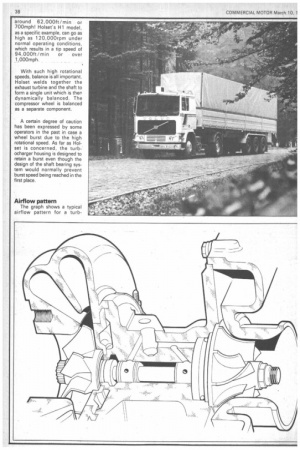
Another way of cramming ore air in involves an exhaust driven turbine connected by a short shaft to a compressor turbine, a combination known as a turbocharger. The pressurised induction is the same as for the mechanical supercharger but it is supplied by the "free" energy of the exhaust gases in the manifold.
It is generally accepted that the first experiments using a turbine with an internal corn.bustion engine were made by Dr Alfred Buchi for Sulzer. His system was introduced commercially in the early twenties and almost all turbocharged engines built today operate on the same principle.
Dr Buchi's ideas were aimed at making as much use as possible of the pressure pulses caused by the sudden surge of gas from each cylinder as the exhaust valve opened. By limiting the diameter and hence the volume of the exhaust manifold, he extracted the maximum amount of work from the moving column of exhaust gases.
As well as increasing the volume of air available for combustion, a pressure induction system has another important advantage — it can be used to scavenge the cylinder at top dead centre. Thus at the tdc position, the centre of the piston crown and the face of the cylinder head receive a blast of (relatively) cool air in areas which are notorious hot spots. I shall return to the subject of air temperature later.
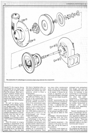
In terms of components, the turbocharger is of a very simple construction, as a glance at the exploded diagram will show. Simplifying this straightforward component even further, we are left with an exhaust driven turbine connected by a solid shaft to a compressor wheel. As the exhaust_ gases pass across the exhaust turbine, the whole assembly is turned rapidly, forcing air into the cylinders and thus increasing the density of the inlet charge over that of a naturally aspirated engine.
Blade profiles
When the exhaust gases hit the end of the exhaust turbine blades, the profile of the blades causes the gas to travel radially inwards. The reverse applies to the compressor wheel where the air enters at the centre. It is then compressed and driven radially outwards and into the inlet manifold via a tangential outlet port.
The turbine housing is manufactured from cast iron while the turbine shaft is mild steel. To keep the mass low, aluminium alloy is used for the compressor wheel while a more exotic Inconel alloy (Nickel/Chrome) is required for the exhaust turbine to cope with the 600' C (1,100G F) of the exhaust gas.
The design of the turbine blades is critical and manufacturers such as Holset need to run long research programmes to develop the aerodynamic profiles. The performance characteristics of a turbocharger are often very dramatic. Rotational speeds of around 80,000rpm are not uncommon which, for a 75mm (3in) turbine wheel, gives a blade tip speed of around 62,000ft / min or 700mph! Holset's H1 model, as a specific example, can go as high as 120,000rpm under normal operating conditions, which results in a tip speed of 94,000ft/min or over 1,000mph.
With such high rotational speeds, balance is all important. Holset welds together the exhaust turbine and the shaft to form a single unit which is then dynamically balanced. The compressor wheel is balanced as a separate component.
A certain degree of caution has been expressed by some operators in the past in case a wheel burst due to the high rotational speed. As far as Holset is concerned, the turbocharger housing is designed to retain a burst even though the design of the shaft bearing system would normally prevent burst speed being reached in the first place.
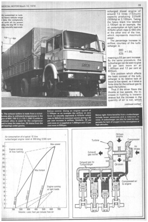
Airflow pattern
The graph shows a typical airflow pattern for a turb ocharged diesel engine of around 12 litres (732cuin) capacity producing 225kW (300bhp) at 2,100rpm. Taking the heavy black line labelled 2,100rpm as an example, the air consumption at light load is 425cfm which rises to 660 cfm at the other end of the line, which represents maximum power.
The percentage increase in airflow, courtesy of the turbocharger, is: 660 =1.55, 425 meaning a 55 per cent increase. By the same procedure, the turbocharger can be seen to give 35 per cent more air at 1,400rpm and 12 per cent at 80Orpm.
One problem which affects the basic concept of the turbocharger is its relative lack of boost at low speed, as it takes a finite time for the exhaust gas to reach the turbine.
Thus if the driver floors the throttle at low speeds, the increase in fuelling is instantaneous but the increase in the quantity of air is not, which results in the engine being over-fuelled for an instant and giving a puff of black smoke from the exhaust. Most fuel injection systems employ some form of boost control which limits the amount of fuel metered at low boost pressures, in order to by-pass this characteristic.
As well as being turbocharged, some diesel engines are charge-cooled. This means exactly what it says, in that the inlet air is cooled before entering the cylinder. Even though the ambient temperature is normal, by the time the inlet air has passed through the turbocharger it is running at about 120°C (248° F) at full speed and load.
Now the power an engine develops is proportional to the mass of the air drawn in and not the volume, which means that the cooler the air, the better the engine likes it. Not only does this have a beneficial effect on the power developed, but it also reduces the exhaust gas temperature, which is often a limiting factor.
Several manufacturers, notably DAF and Perkins, cool the air aft of the turbocharger by passing it through an auxiliary air-to-air radiator mounted in front of the conventional water radiator. In some chassis this results in some pretty tortuous pipework but it produces an effective drop in inlet temperature. (DAF claims a reduction of around 50°C (122°F) on the turbocharged and chargecooled DKS engine).
One unwanted attribute of the turbocharger is that operators tend to blame the unit immediately any symptom such as loss of power, black smoke or high fuel consumption raises its head. Although it is certainly possible for a turbocharger to cause these symptoms, there are many other components which can also be responsible. Onqe a turbocharger is matched to an engine, it cannot be adjusted or regulated, so only mechanical damage or blockage due to dirt can impair its performance.
HOLSET recommends that the following points be checked before a turbocharger is replaced: Air filter — a blocked filter wili restrict the airflow to the compressor Joints — check for gas leakage at the exhaust manifold or turbine inlet and air leaks on inlet side.
Oil leakage — the prime cause of oil leakage from the turbocharger unit is a blocked air filter Fuel injection equipment — the injectors or the pump can more often than not be the cause of any problems.
Nowadays most diesel engine manufacturers offer turb ocharged units somewhere their ranges, with some be: more enthusiastic than othE Volvo, for example, is tote committed to turbochargi whereas Fiat goes complet the other way with automotive turbocharg diesels currently being offer' The majority are somewhere the middle, listing both tu °charged and natura aspirated units, depending the rating required.
Several manufacturers th that a turbocharger will be sential to meet proposed en sion regulations. When I sip' to Arch Joyner of Cummins I year, he told me: "There may some technique for a natun aspirated engine to do this I Cummins don't know it."
It may be that forced ind tion engines will take over cc pletely during the next decad