


A VACUUM-ACTUATED BRAKE WITH FEW PARTS.
Page 28
If you've noticed an error in this article please click here to report it so we can fix it.
A R6sume of Recently Published Patent Specifications.
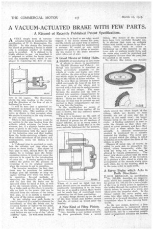
AVERY simple form of vacuumactuated brake is described in the specification of W. 0. Kennington, No. 228,225. In this design the inventor has aimed at producing a brake in which only a minimum number of working parts is entailed. It is claimed to be highly efficient in use. As described, it is proposed to utilize for brake operation the butterfly valve which is employed in regulating the flow of mix tore to the engine. The illustration (4hows, the pipe leading to the engine, and the direction of the flow of air is Indicated by arrows. It will be seen that a spherical enlargement is formed in the pipe where the throttle acts. The position of the valve as shown is that occupied when 'the engine is running at its very slowest, or just turning over. When in this position, there would be no suction in the pipe leading from the cylinder which actuates the brake by vacuum, but, if a slightly further movement is given to the valve, it will open up communication with the upper part of the induction pipe an that leading from the brake-operating cylinder, and thus induce Movement of the piston and, consequently, cause the brakes to be applied. A IT-shaped pipe is provided to ventilate the cylinder and thus allow the piston to move freely. The object of this pipe is that, should there by any chance be a leakage past the brakeoperating piston, it would not cause the mixture to be upset by the introduction of extra air. A strong spring is fitted behind the piston for the purpose of returning it to its original position when the vacuum is not in operation. • The inventor mentions the fact that there may be provision for sufficient leakage past the butterfly to keep the engine turning over while the brake is In operation. Several methods of operating the butterfly are described, and the fact that the brake can be operated either by hand or foot, as well as by the vacuum piston, is mentioned. In a brake such as this there is practically no limit to the power that can be obtained from the vacuum of the induction pipe, as it is merely a matter of the area of the piston employed. In our opinion any such brake is vastly improved if a sensitive element be introduced, so that the driver can, by pressing harder or lighter 'on his pedal, feel what amount of pressure he is exerting on his brakes. Without this such brakes are apt to be of the " all-ornothing " type. As with most brakes of
C44
this class, it is hard to see what would happen if the driver missed his gear, and the vehicle got under way in neutral, as no means is provided for maintaining a vacuum. It would go very much against the grain of a driver to accelerate his engine to the brake actuation paint when out of gear.
.A Good Means of Oiling Hubs. A MEANS of introducing oil into hubs of wheels is shown in specification No. 228,465 (Renton and Fisher).Although this inyention is described as being particularly adaptable to the wheels of trucks and bogies and other -ail vehicles, the plan strikes us as being one which might be applied with advantage to the wheels of motor vehicles. It will be seen that an annulu,s is formed which surrounds the boss of the hub on the outer side of the wheel, and is covered with a hub cap in such a manner thab no oil can escape. The space between the annulus and the boss is divided into separate compartments by means of a number of radial webs as shown. Holes are drilled in the boss so that any oil that may be scooped up and carried in these compartments can find its way into the bearing. In the specification no means of securing the wheel from coming off its axle is shown, but any ordinary means can be employed. There is a tendency on the part of many designers to encourage the use of oil instead of grease for all bearings of motor vehicles, as in so many cases it has shown beyond doubt that it is the more suitable lubricant for the purpose.
Where oil is used we think that this plan should prove an excellent means of continually introducing it to the bearing, as, at so small a radius, there would not be much fear of centrifugal force preventing the oil froth gravitating.
A slight flange thrown up on the end of the boss would still further ensure that the oil picked up would enter the bearing.
A New Kind of Fibre Pinion.
THE British Thomson-Houston Co., Ltd., describe a new method of forming fibre gearwheels from a woven ribbon. The details of the invention have been very carefully thought out. It is obvious that were an ordinary ribbon bent round, as shown in an illustration, there would be either a thickening up of the material on the inner side, or puckers would form, and the outer edge would be stretched and consequently thinner than the part, that lies nearest to the centre.
To obviate this defect, the threads
-Odell extend the whole length of the ribbon, which are known as weft threads, are not of even size (as is shown in the small view), the larger threads being at the outer part of the circle. A binding substance is used to unite the threads so that when subjected to great pressure and heat, they bind into a rhass which has great strength. A phenolic condensation Product is mentioned as a suitable material for binding. The metal portion around which the ribbon is coiled is kniirled so as to allow the fibres of the ribbon to grip it. Flanges of metal can, of course, be added to each side to strengthen the wheel, either temporarily while the teeth are being cut, or they may be allowed to reinain permanently. The lower view shows amheel with the teeth cut. The main object of the invention is to produce a fibre wheel in which the arrangement of the threads which cross each other, due to the weaving, shall be in the same order in each tooth.
A Servo Brake which Acts in Both Directions.
LOUIS RENAULT, in specification
No. 226,669, describes an improveinent which has recently been added to hiS patent No. 197,332 for a servo brake of the type in which power is applied to the brakes through the medium of a disc clutch driven by means of a worm and wheel from the propeller shaft. In the former patent the servo action only came into play when the vehicle was moving in a forward direction and was inoperative when it was running backwards. In the new design, however, a freewheel mechanism is introduced which only comes into operation when running backwards, and by a somewhat complicated arrangement actuates the brakes.