


Patents Completed.
Page 22
If you've noticed an error in this article please click here to report it so we can fix it.
Complete specifications of the following patents will be sent to any address in the United Kingdom upon receipt of eightpence per copy at the Sales Branch, Patent Office, Holborn, W.C.
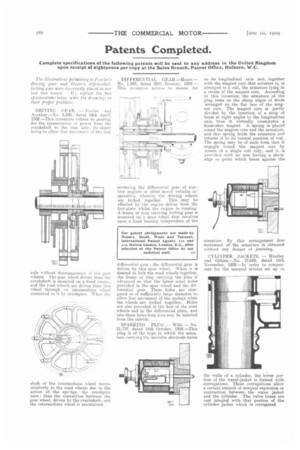
The illustrations pertaining 10 Fowler's driving gear and iloare's differentiallocking gear were incorrectly placed in our last two issues. Fre reprint the two specifications below witit the drawings in their proper positions.
DRIVING GEAR. — Fowler and Another.—No. 8,640, dated 18th April, 1908.—This invention relates to gearing for the transmission of power from the crankshaft to the rear axle, its object being to allow free movement of the rear axle without disengagement of the gear wheels. The gear wheel driven from the crankshaft is mounted on a fixed centre, and the road wheels are driven from this wheel through an intermediate wheel connected to it by crankpins. When the shaft of the intermediate wheel move, relatively to the road wheels due to the action of the springs, the crankpins turn ; thus the connection between the gear wheel, driven by the crankshaft, and the intermediate wheel is maintained. DIFFERENTIAL GEAR—Hoare.No. 1,899, dated 26th January, 1909.— This invention relates to means for rendering the differential gear of traction engines or other motor vehicles inoperative, whereby the driving wheels are locked together. This may be effected by the engine driver from the foot-plate whilst the engine is running. A frame or ring carrying locking pins is mounted on a spur wheel that revolves upon a fixed bearing independent of the differential gear ; the differential gear is driven by this spur wheel. When it is desired to lock the road wheels together, the frame or ring carrying the pins is advanced so that the latter enter holes provided in the spur wheel and the differential gear. These holes are elongated or of sufficiently large diameter to allow free movement of the springs when the wheels are locked together. Holes are also provided in the hub of the road wheels and in the differential plate, and into these holes long pins may be inserted from the outside.
SPARKING PLUG. — Wild. — No. 21,757, dated 14th October, 1908.—This plug is of the type in which the armature carrying the movable electrode turns
on its longitudinal axis and, together with the magnet core that actuates it, is arranged in a coil, the armature lying in a recess of the magnet core. According to this invention the armature of the plug rests on the sharp edges of studs arranged on the flat face of the magnet core. The magnet core is partly divided by the insertion of a strip of brass at right angles to the longitudinal axis, thus it virtually constitutes a horse-shoe magnet. A spring is placed round the magnet core and the armature, and this spring holds the armature and returns it to its normal position of rest. The spring may be of such form that it engages round the magnet core by means of a single coil only, and it is provided with an arm having a sharp edge or point which bears against the
armature. By this arrangement free movement of the armature is obtained without any danger of jamming.
CYLINDER JACKETS. — Hindlev and Others.—No. 10,689, dated 16th November. 1908.—In order to compensate for the unequal strains set up in the walls of a cylinder, the lower portion of the water-jacket is formed with corrugations. These corrugations allow a certain amount of unequal expansion or contraction between the water jacket and the cylinder. The valve boxes are cast integral with that portion of the cylinder jacket which is corrugated.